My Cart
0 items
Genuine Automation Parts | Worldwide Express Delivery | 12-Month Warranty — [GET A QUOTE]

Configured for high-speed logic execution within DCS platforms, the YOKOGAWA NFCP100-S00 S3 (NFCP100-S00 CPU Module) provides direct physical/electrical execution of control algorithms and I/O data processing.
Availability: Low stock: 99 left
Reliable Worldwide Delivery
30-Day Money-Back Guarantee
Need more details? Read our fullShipping PolicyandRefund Policy.


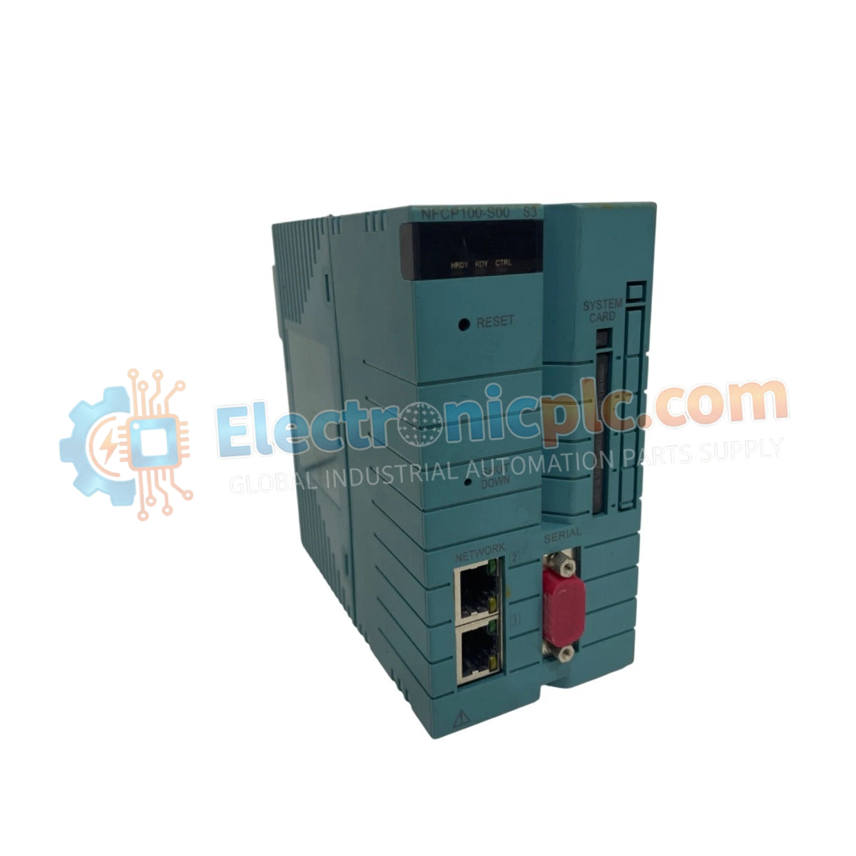
Configured for high-speed logic execution within DCS platforms, the YOKOGAWA NFCP100-S00 S3 (NFCP100-S00 CPU Module) provides direct physical/electrical execution of control algorithms and I/O data processing.
The NFCP100-S00 identifies the base CPU hardware configuration, while the S3 suffix denotes the specific revision/series iteration for compatibility with current Yokogawa control infrastructure.
| Parameter | Specification |
|---|---|
| Model | NFCP100-S00 S3 |
| Brand | YOKOGAWA |
| Origin | japan |
| Weight | 0.5 kg |
| Dimensions | 2.2 cm x 12.4 cm x 12.6 cm |
| Operating Temp | Standard Industrial Range |
| Power Consumption | Subject to backplane loading |
| Processor Type | Field Control Station (FCS) CPU |
The NFCP100-S00 S3 module facilitates integration within Yokogawa process control environments, supporting 4-20 mA HART loop protocol management to ensure precise field device communication. The module maintains signal integrity across the backplane by utilizing high-density channel-to-channel isolation, preventing electrical noise ingress during complex analog-to-digital conversions. Cold junction compensation (CJC) is managed internally for thermocouple inputs, ensuring accuracy in temperature-sensitive loop control applications.
Q: Is this CPU module compatible with previous firmware versions of the NFCP100 series?
A: Compatibility is dependent on the system backplane revision. Confirm firmware flash compatibility with the existing control station environment before hardware insertion.
Q: Does the module support hot-swapping during active control operations?
A: Hot-swapping the NFCP100-S00 S3 is restricted to prevent potential bus communication errors or system resets; ensure the station is in a safe, non-active state prior to physical removal or installation.


