
My Cart
0 items
Genuine Automation Parts | Worldwide Express Delivery | 12-Month Warranty — [GET A QUOTE]

Configured for discrete control in STARDOM autonomous control systems, the YOKOGAWA NFDR541-P00 S2 (NFDR541 Relay Output Module) provides direct physical/electrical execution. This hardware component manages 16 independent dry-contact channels, facilitating...
Availability: In stock
Reliable Worldwide Delivery
30-Day Money-Back Guarantee
Need more details? Read our fullShipping PolicyandRefund Policy.


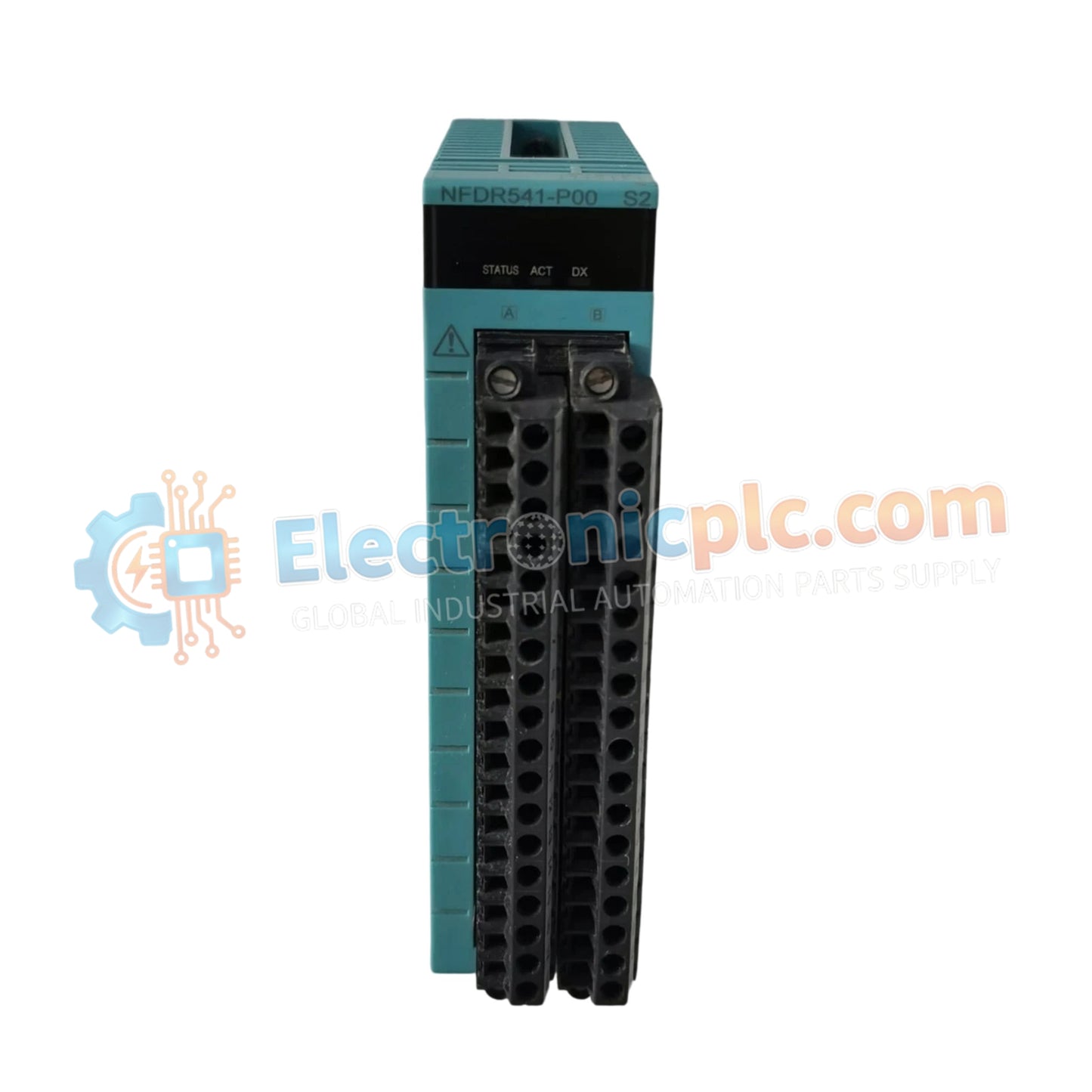
Configured for discrete control in STARDOM autonomous control systems, the YOKOGAWA NFDR541-P00 S2 (NFDR541 Relay Output Module) provides direct physical/electrical execution. This hardware component manages 16 independent dry-contact channels, facilitating the switching of solenoids, interposing relays, and indicators within FCN or FCJ control platforms.
| Parameter | Specification |
|---|---|
| Model | NFDR541-P00 S2 |
| Brand | YOKOGAWA |
| Origin | JAPAN |
| Weight | 0.3 kg |
| Dimensions | 3.3 cm x 12.7 cm x 12.7 cm |
| Operating Temp | -10 to 55 deg C |
| Power Consumption | 780 mA (at 5 VDC) |
| Output Channels | 16 |
| Output Type | Relay (Dry Contact) |
| Max Current (DC/AC) | 5 A (DC) / 3 A (AC) |
The NFDR541-P00 S2 provides robust electrical isolation between the internal control circuitry and the field-side output contacts. With an isolation voltage rating of 2000 V AC, this module prevents high-voltage transients on the field side from propagating back to the FCN/FCJ controller bus. The dry-contact architecture allows for versatile integration across multiple voltage levels, supporting DC loads up to 110 V and AC loads up to 240 V without requiring external signal conversion stages.
Q: Does the NFDR541-P00 S2 support hot-swapping for maintenance?
A: Hot-swapping is permissible provided the system architecture and base unit configuration allow for online module replacement; however, the field power must be isolated from the relay contacts before removal to ensure operator safety and prevent contact arcing.
Q: Are the 16 output channels independently addressable and isolated from one another?
A: The channels are independently addressable for control logic; however, users must verify the common terminal grouping on the terminal block to confirm isolation boundaries between specific channel banks.


