My Cart
0 items
Genuine Automation Parts | Worldwide Express Delivery | 12-Month Warranty — [GET A QUOTE]

The Yokogawa NFDR541-P00, also cataloged as the NFDR541 Relay Output Module, operates as a dedicated hardware component for discrete signal switching and field device activation within Centum CS and Centum...
Availability: Low stock: 99 left
Reliable Worldwide Delivery
30-Day Money-Back Guarantee
Need more details? Read our fullShipping PolicyandRefund Policy.


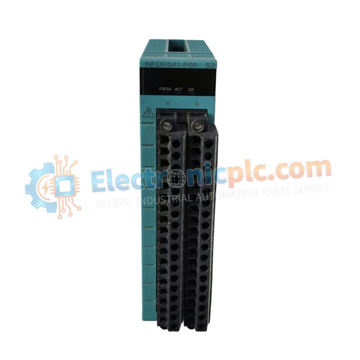
The Yokogawa NFDR541-P00, also cataloged as the NFDR541 Relay Output Module, operates as a dedicated hardware component for discrete signal switching and field device activation within Centum CS and Centum VP control platforms.
The NFDR541-P00 model identifier indicates the standard hardware configuration for the relay output interface. The "-P00" suffix denotes the basic factory-shipped version intended for general-purpose rack-mounted operation, ensuring compatibility with standard Centum VP I/O backplanes without specialized conformal coating or extended temperature environmental modifications.
| Parameter | Specification |
|---|---|
| Model | NFDR541-P00 |
| Brand | Yokogawa |
| Origin | Japan |
| Weight | 0.3 kg |
| Dimensions | 3.3 cm x 12.7 cm x 12.7 cm |
| Operating Temp | 5 deg C to 40 deg C |
| Power Consumption | 5 V DC (internal backplane) |
| Output Type | Relay Contact |
| Compatibility | Centum CS, Centum VP |
As part of the Yokogawa DCS I/O architecture, this module provides discrete output execution to field actuators. While the module facilitates interposing control, it requires careful consideration regarding channel-to-channel isolation limits. In high-demand control loops, ensure that current suppression is implemented for inductive loads (e.g., solenoid valves or contactors) to prevent back-EMF damage to the relay contact surfaces.
Q: What is the maximum switching current supported by the onboard relays?
A: Users must refer to the terminal block ratings and internal relay specifications; typically, these modules are designed for low-to-medium power signal switching. Inductive loads exceeding 1 A should be isolated via an external secondary relay to preserve module longevity.
Q: Is this module compatible with live module replacement (hot-swap)?
A: Yes, the NFDR541-P00 is designed for hot-swapping within a powered Centum VP node. Ensure the system configuration is updated to ignore state changes during the extraction and insertion process to prevent unintended output toggling.


