
My Cart
0 items
Genuine Automation Parts | Worldwide Express Delivery | 12-Month Warranty — [GET A QUOTE]

Configured for high-density signal acquisition in CENTUM control networks, the YOKOGAWA NFDV151-P60/B5S00 (NFDV151 Digital Input Module) provides direct physical signal processing for 32 discrete input channels.
Availability: In stock
Reliable Worldwide Delivery
30-Day Money-Back Guarantee
Need more details? Read our fullShipping PolicyandRefund Policy.


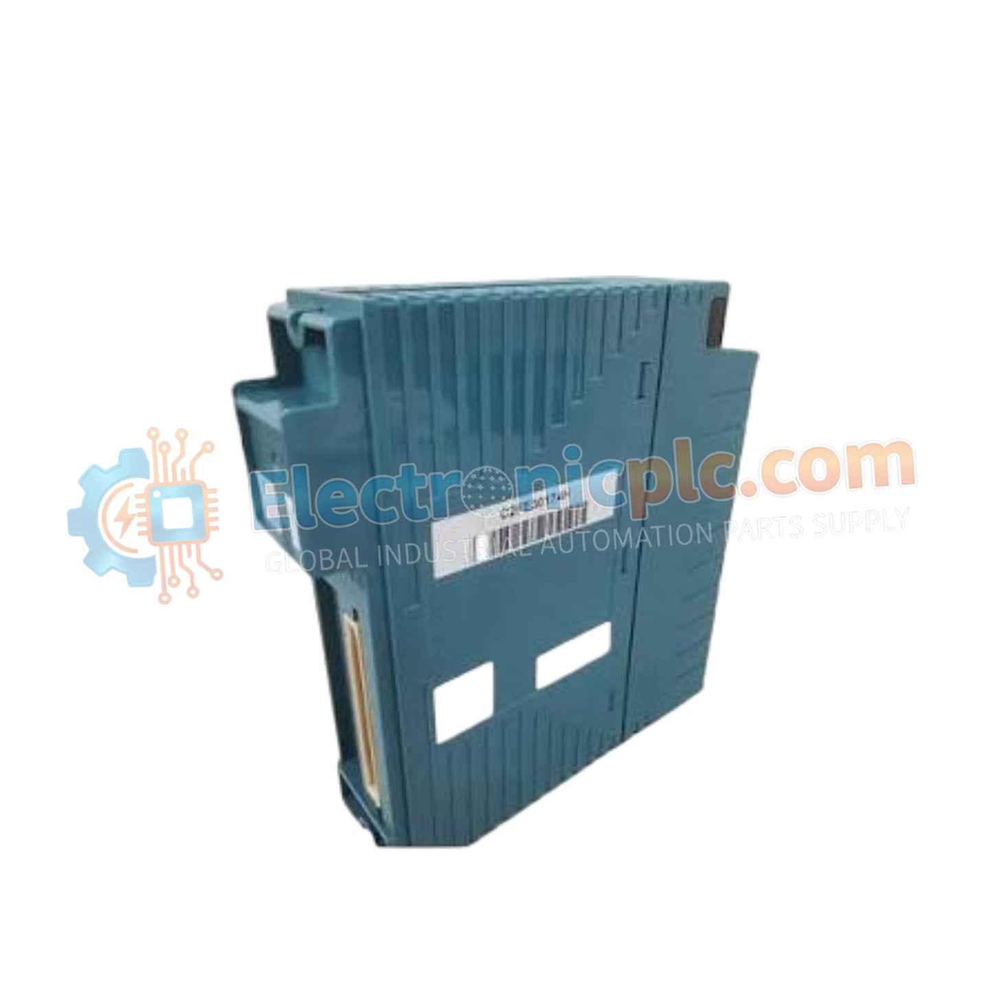
Configured for high-density signal acquisition in CENTUM control networks, the YOKOGAWA NFDV151-P60/B5S00 (NFDV151 Digital Input Module) provides direct physical signal processing for 32 discrete input channels.
| Parameter | Specification |
|---|---|
| Model | NFDV151-P60/B5S00 |
| Brand | YOKOGAWA |
| Origin | Japan |
| Weight | 0.3 kg |
| Dimensions | Standard NFDV Series form factor |
| Operating Temp | Not specified (Standard industrial range) |
| Power Consumption | 500 mA (5 V DC) |
| Input Channels | 32 |
| Rated Voltage | 24 V DC |
| Input ON Voltage | 18 to 26.4 V DC |
| Input OFF Voltage | 5.0 V DC or less |
| Withstanding Voltage | 2000 V AC (Input-System) |
The NFDV151-P60/B5S00 utilizes integrated opto-isolation to maintain signal integrity across all 32 channels. This architecture ensures galvanic isolation between the field input circuits and the internal system bus, preventing cross-channel interference and protecting system components from transient voltage surges. The module supports a rated input voltage of 24 V DC with a defined switching threshold to ensure stable detection of binary states in industrial environments.
Q: Is this module capable of hot-swapping during active system operation?
A: Hot-swapping the NFDV151 module is permissible only when the associated field power is isolated and the system software is configured for non-interruptive module replacement. Ensure the rack backplane is powered before module insertion to avoid initialization errors.
Q: How should the common lines be managed to maintain the 500 V AC isolation rating?
A: Proper segregation of common return paths is required to maintain the 500 V AC isolation between channel groups. Shielded cabling should be used for all inputs, with the shield connected to the chassis ground at the cabinet entry point to suppress induced electromagnetic noise.


