My Cart
0 items
Genuine Automation Parts | Worldwide Express Delivery | 12-Month Warranty — [GET A QUOTE]

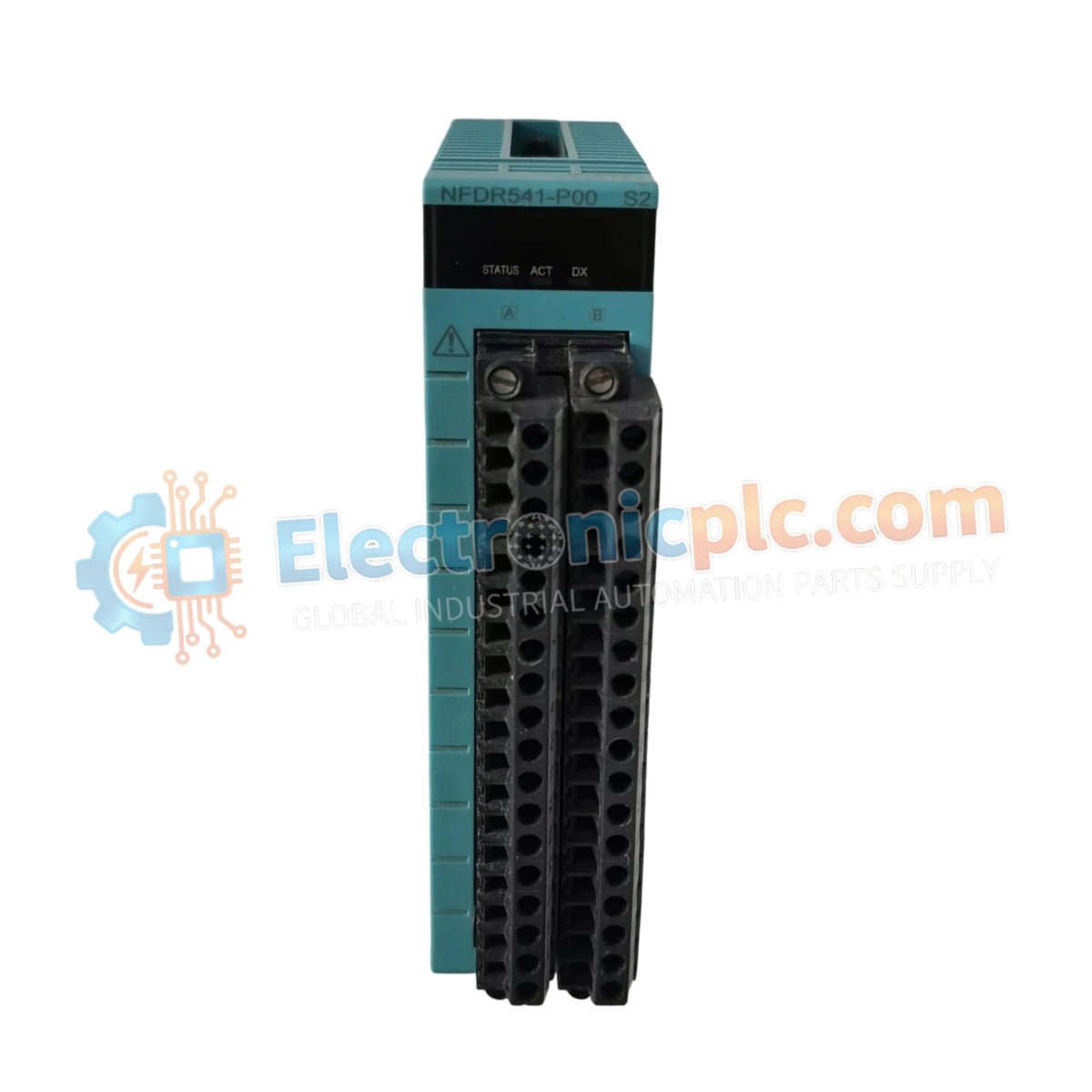
Configured for high-density signal acquisition in DCS platforms, the Yokogawa NFDV151-P60 (NFDV151-P60 Digital Input Module) provides direct physical signal processing for 32 discrete input channels.
| Parameter | Specification |
|---|---|
| Model | NFDV151-P60 |
| Brand | Yokogawa |
| Origin | Japan |
| Weight | 0.3 kg |
| Dimensions | 100 mm x 30 mm x 110 mm |
| Operating Temp | Consult system environmental specifications |
| Power Consumption | 500 mA (5 V DC) |
| Input Channels | 32 |
| Rated Input Voltage | 24 VDC |
| Input ON Voltage | 18 to 26.4 VDC |
| Input OFF Voltage | 5.0 VDC or less |
| Response Time | 8 ms or less (status input) |
The architecture of the module ensures signal integrity through comprehensive electrical isolation, featuring a 2000 V AC withstanding voltage rating between input signals and the system bus. The module supports common minus (-) grouping for every 16 channels, protected by a 500 V AC withstanding voltage isolation barrier. Field input currents are regulated at 4.1 mA (at rated voltage) to minimize thermal accumulation. Logic processing logic is optimized for both static status input and dynamic push-button operations, with defined input response times of 8 ms for status signals and a minimum 20 ms ON detection duration for push-button inputs to eliminate contact bounce transients.
Q: Is this module capable of performing hot-swap operations within the I/O rack?
A: Hot-swapping is dependent on the specific DCS backplane and power distribution configuration. Verify that the system firmware and chassis power architecture support online insertion and removal for this module series before performing maintenance.
Q: What is the maximum switching frequency supported for push-button inputs?
A: The module is engineered for a maximum ON/OFF cycle of 25 Hz when configured for push-button input mode.