My Cart
0 items
Genuine Automation Parts | Worldwide Express Delivery | 12-Month Warranty — [GET A QUOTE]

The YOKOGAWA NFPW442-10, also cataloged as the NFPW442-10 Power Supply Module, operates as a dedicated hardware component for power regulation within Yokogawa STARDOM FCN, FCJ, and FCN-RTU control platforms. This...
Availability: Low stock: 99 left
Reliable Worldwide Delivery
30-Day Money-Back Guarantee
Need more details? Read our fullShipping PolicyandRefund Policy.


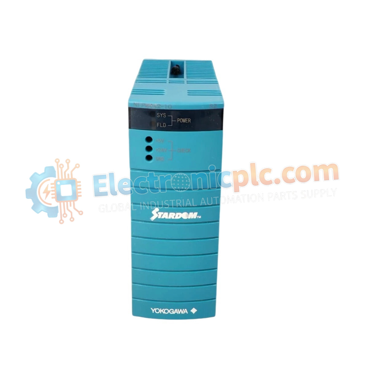
The YOKOGAWA NFPW442-10, also cataloged as the NFPW442-10 Power Supply Module, operates as a dedicated hardware component for power regulation within Yokogawa STARDOM FCN, FCJ, and FCN-RTU control platforms. This module executes the conversion of 24 VDC input into regulated 5 VDC and internal system voltages, maintaining the electrical potential required for a full rack of CPU and I/O modules.
| Parameter | Specification |
|---|---|
| Model | NFPW442-10 |
| Brand | Yokogawa |
| Origin | Japan |
| Weight | 0.6 kg |
| Dimensions | Standard FCN module form factor |
| Input Voltage | 24 VDC +/- 10% |
| Output Voltage | 5 VDC and internal system rails |
| Operating Temp | -20 deg C to +60 deg C |
| Cooling Method | Passive convection |
The NFPW442-10 is engineered for high-availability control environments, featuring RAS (Reliability, Availability, Serviceability) capabilities, including CPU self-diagnostics and localized temperature monitoring. The module supports galvanic channel-to-channel isolation to prevent common-mode noise propagation across the backplane. Its design maintains strict 5 VDC output regulation under fluctuating load conditions, ensuring data integrity for I/O module communication and field control bus synchronization.
Q: Does the NFPW442-10 support hot-swapping during system operation?
A: Yes, this module is hot-swappable. It can be replaced while the controller is powered, provided that a redundant power configuration is active or the process safety requirements permit temporary module removal.
Q: Is this module compatible with duplex (redundant) power setups?
A: Yes, the NFPW442-10 supports dual power supply configurations when installed in compatible base modules (NFBU200 or NFBU050). The system performs automatic failover if the primary module output drops below nominal thresholds.


