My Cart
0 items
Genuine Automation Parts | Worldwide Express Delivery | 12-Month Warranty — [GET A QUOTE]

Configured for power regulation and distribution in DCS platforms, the YOKOGAWA NFPW 444-10 (NFPW 444-10 Power Supply Module) provides direct physical/electrical execution. This module functions as a primary power conversion...
Availability: Low stock: 99 left
Reliable Worldwide Delivery
30-Day Money-Back Guarantee
Need more details? Read our fullShipping PolicyandRefund Policy.

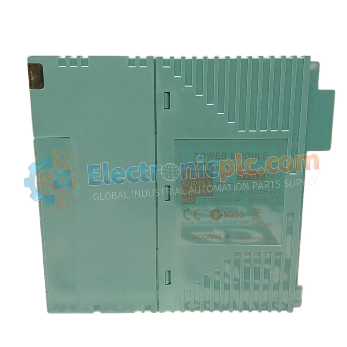
Configured for power regulation and distribution in DCS platforms, the YOKOGAWA NFPW 444-10 (NFPW 444-10 Power Supply Module) provides direct physical/electrical execution. This module functions as a primary power conversion component, stabilizing incoming supply voltage to generate the regulated DC output required for the operational integrity of backplane-mounted control cards and field instrumentation.
The model identifier NFPW 444-10 designates the specific hardware configuration for this power supply unit. This unit is calibrated for compatibility within standard Yokogawa DCS chassis, ensuring precise mechanical alignment and electrical interface synchronization with the system backplane.
| Parameter | Specification |
|---|---|
| Model | NFPW 444-10 |
| Brand | Yokogawa |
| Origin | Japan |
| Weight | 0.4 kg |
| Dimensions | 5.5 cm x 15.0 cm x 11.2 cm |
| Operating Temp | 0 deg C to 50 deg C |
| Power Consumption | Nominal load dependent |
The NFPW 444-10 is designed to maintain consistent voltage rails within the control system, which is necessary for the stability of the 4-20 mA HART loop protocol. The internal circuitry utilizes channel-to-channel isolation to prevent electrical noise and ground loops from impacting signal accuracy. Additionally, the unit incorporates cold junction compensation (CJC) capabilities to ensure that temperature-dependent signals remain precise across the module's operating environment.
Q: Is this power supply module compatible with hot-swapping procedures?
A: The NFPW 444-10 supports hot-swapping if the rack backplane and chassis configuration are rated for live-insertion. Verify that the system software acknowledges the module removal to prevent error flags in the diagnostic registry.
Q: How should the module be configured for redundant power applications?
A: For redundancy, ensure the NFPW 444-10 is installed alongside an identical unit in a dual-slot configuration. The system backplane manages the automatic switchover logic; ensure the input power feeds are derived from separate distribution circuits to maximize uptime.

