My Cart
0 items
Genuine Automation Parts | Worldwide Express Delivery | 12-Month Warranty — [GET A QUOTE]

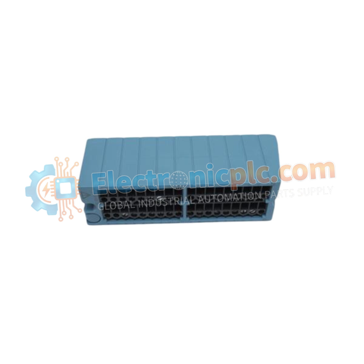
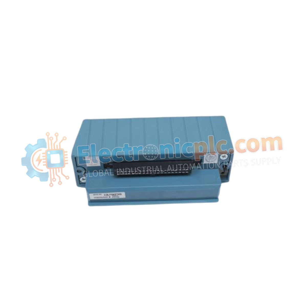
Configured for analog signal acquisition in STARDOM controller platforms, the Yokogawa NFTA4S-10 (NFTA4S-10 Analog Input Module) provides direct physical/electrical execution of 16-channel analog-to-digital signal conversion.
| Parameter | Specification |
|---|---|
| Model | NFTA4S-10 |
| Brand | Yokogawa |
| Origin | Japan |
| Weight | 0.2 kg |
| Dimensions | Standard STARDOM I/O form factor |
| Operating Temp | -40 to +80 deg C |
| Power Consumption | Refer to STARDOM backplane power budget |
| Input Channels | 16 independent |
| Input Types | 4-20 mA DC, 1-5 V DC |
| Resolution | 16-bit |
| Accuracy | +/- 0.1% of full scale |
The module functions as the primary interface for field instrumentation, accepting standard 4-20 mA or 1-5 V DC inputs and performing high-resolution conversion for controller processing. While the architecture utilizes non-isolated channels, it maintains a consistent 16-bit conversion depth across all 16 inputs to ensure process data granularity. The module is engineered to operate within an industrial temperature spectrum, ensuring the analog-to-digital conversion circuits remain stable under varying environmental conditions without degradation of the +/- 0.1% accuracy threshold.
Q: Does the NFTA4S-10 support hot-swapping within the controller rack?
A: The ability to perform hot-swapping depends on the specific STARDOM rack backplane and power distribution system. Consult the system hardware manual to confirm support for online maintenance procedures for this module.
Q: How is the input type selected for the 16 channels?
A: Input configuration for 4-20 mA or 1-5 V DC is typically managed through the STARDOM engineering software parameters, which control the internal signal path and shunt resistance logic for the module.