
My Cart
0 items
Genuine Automation Parts | Worldwide Express Delivery | 12-Month Warranty — [GET A QUOTE]

The Yokogawa PFCS-S5120 S1, also cataloged as the PFCS-S5120 Field Control Station (FCS) Module, operates as a dedicated hardware component for localized process execution and data exchange within distributed control...
Availability: Low stock: 99 left
Reliable Worldwide Delivery
30-Day Money-Back Guarantee
Need more details? Read our fullShipping PolicyandRefund Policy.


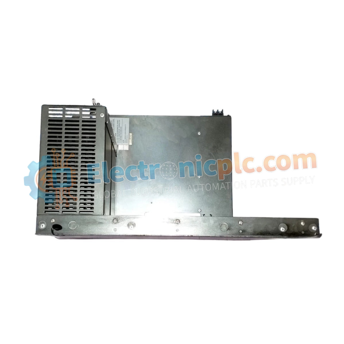
The Yokogawa PFCS-S5120 S1, also cataloged as the PFCS-S5120 Field Control Station (FCS) Module, operates as a dedicated hardware component for localized process execution and data exchange within distributed control system (DCS) networks. This module manages logic processing and signal interfacing between field instrumentation and the primary supervisory control layer.
| Parameter | Specification |
|---|---|
| Model | PFCS-S5120 S1 |
| Brand | Yokogawa |
| Origin | Japan |
| Weight | Not specified |
| Dimensions | Standard rack mount |
| Operating Temp | Industrial standard |
| Power Consumption | 320 VA (190 W) |
| Input Voltage | 24 V DC |
| Output Voltage | 220-240 V AC |
| Frequency | 50/60 Hz +/- 3 Hz |
The PFCS-S5120 integrates directly into the DCS architecture, facilitating deterministic data throughput between field-level devices and higher-tier controllers. Utilizing standard 4-20 mA HART loop protocol handling, the module maintains signal integrity across long-distance analog transmission lines. Channel-to-channel isolation is maintained to prevent common-mode noise propagation, ensuring that localized electrical faults do not affect adjacent control loops. Cold junction compensation (CJC) routines are processed locally for temperature input modules, ensuring precise process variable scaling before data transmission across the control bus.
Q: Does the PFCS-S5120 S1 module support hot-swapping under normal operational load?
A: Hot-swapping is restricted. The power supply must be isolated from the specific module slot before physical removal to prevent backplane bus transients or component damage.
Q: How does the module handle signal noise in the control loop?
A: The module employs galvanic isolation techniques and standard shielding practices to mitigate electromagnetic interference. Ensure that cable shields are grounded at a single point to prevent ground loops.


