My Cart
0 items
Genuine Automation Parts | Worldwide Express Delivery | 12-Month Warranty — [GET A QUOTE]

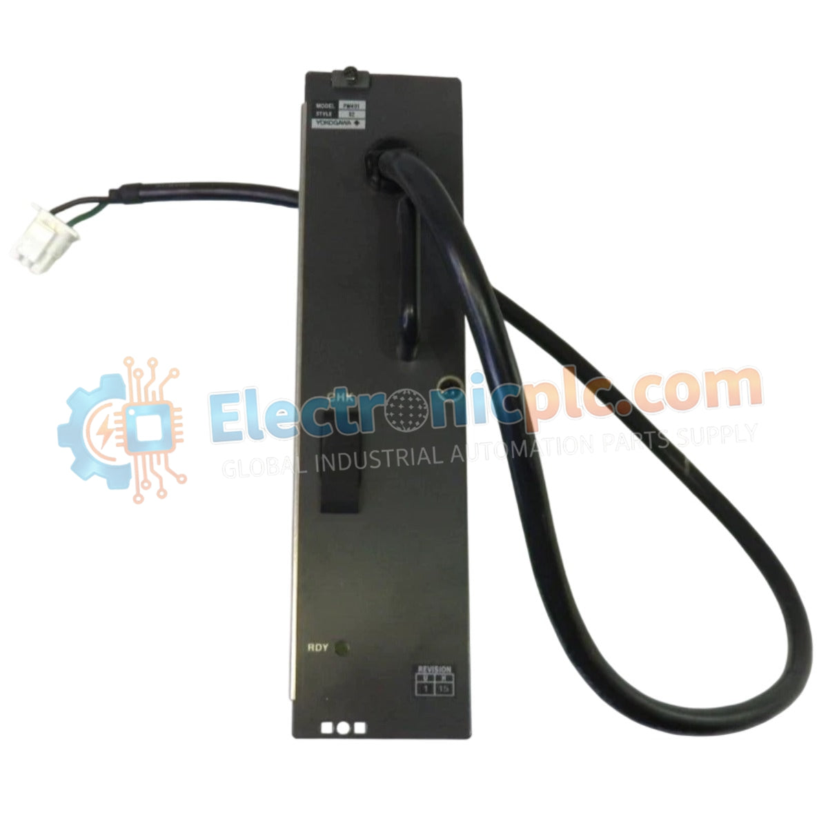
Configured for power conversion in DCS process control platforms, the YOKOGAWA PW401 S2 (PW401 S2 Power Supply Module) provides direct physical/electrical execution.
| Parameter |
| Parameter | Specification |
| Model | PW401 S2 |
| Brand | YOKOGAWA |
| Origin | Subject to factory batch |
| Weight | 1.54 kg |
| Dimensions | 5.1 cm x 20.3 cm x 20.3 cm |
| Operating Temp | Standard industrial ambient range |
| Power Consumption | 102 W |
| Input Voltage | 100-120 VAC, 50/60 Hz |
| Output Voltage | 5.1 VDC |
| Output Current | 20 A |
The unit integrates specialized circuitry for channel-to-channel isolation and voltage regulation required in DCS instrumentation loops. To maintain the specified output stability, the power supply utilizes internal feedback loops to compensate for variations in line voltage. The 5.1 VDC output is maintained with low ripple characteristics, facilitating stable operation for logic-level circuitry and communication modules within the YOKOGAWA ecosystem. Proper thermal management is required to prevent derating when operating at high ambient temperatures, necessitating adequate cabinet ventilation to ensure component longevity.
Q: Can this module be used in a 220-240 VAC power environment?
A: The PW401 S2 is specified for 100-120 VAC input. Utilizing this module with a 220-240 VAC supply without an appropriate step-down transformer will result in failure of the primary input stage.
Q: How is the output current monitored under maximum load?
A: The module is designed for a constant 20 A output at 5.1 VDC. Protection circuitry is embedded to limit current during transient overloads; if the 102 W threshold is exceeded, the unit will engage current limiting to prevent thermal damage to the internal output stage.