My Cart
0 items
Genuine Automation Parts | Worldwide Express Delivery | 12-Month Warranty — [GET A QUOTE]

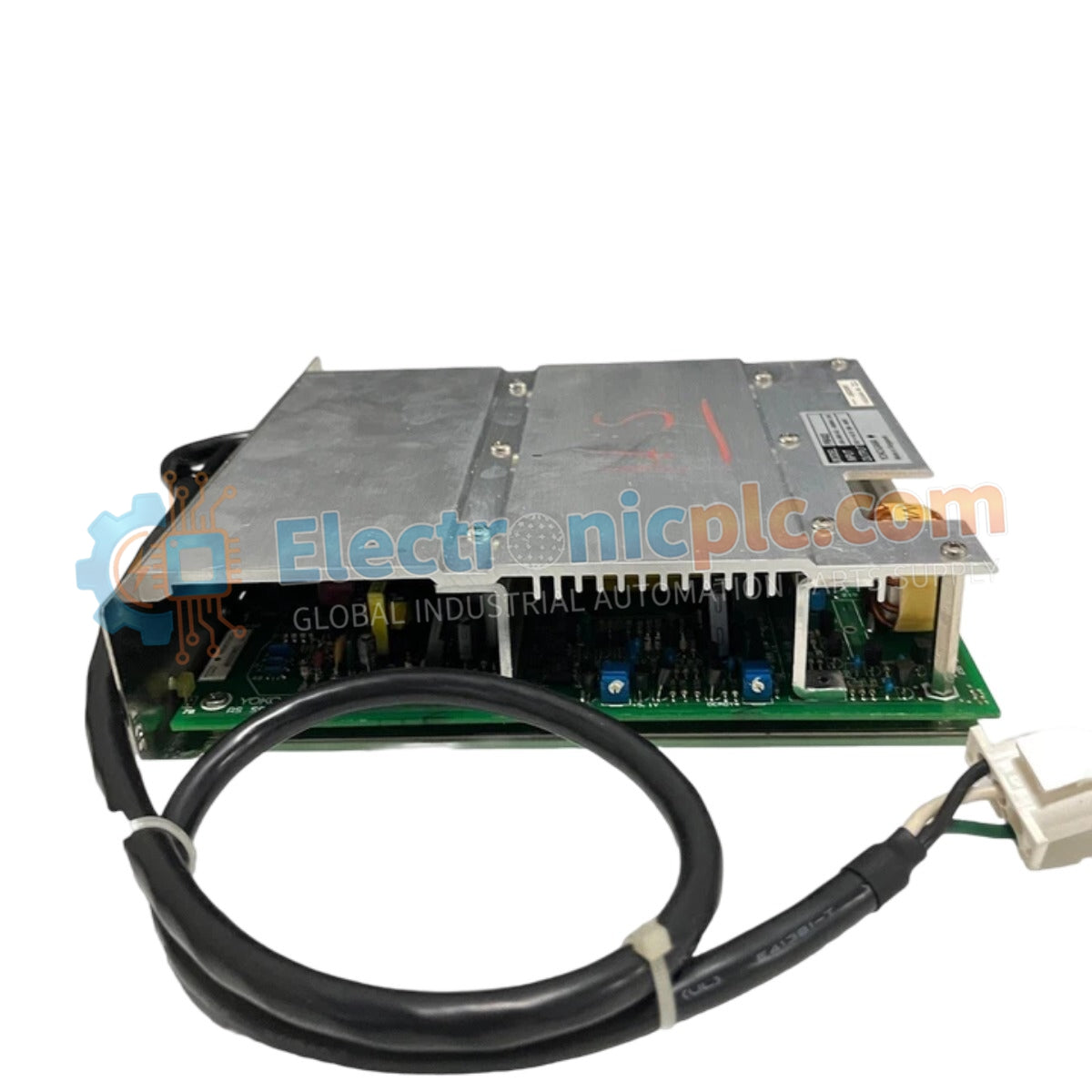
Configured for power conversion in DCS process control platforms, the YOKOGAWA PW402 S2 (PW402 S2 Power Supply Module) provides direct physical/electrical execution.
| Parameter |
| Parameter | Specification |
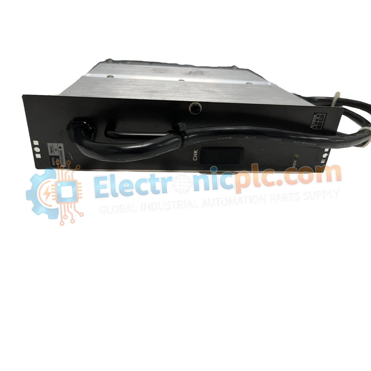
| Model | PW402 S2 |
| Brand | YOKOGAWA |
| Origin | Japan |
| Weight | 2 kg |
| Dimensions | 5.1 cm x 22.9 cm x 20.3 cm |
| Operating Temp | Standard industrial ambient range |
| Power Consumption | Load dependent |
The module integrates specialized circuitry for channel-to-channel isolation and voltage regulation required in DCS instrumentation loops. To maintain consistent output performance, the power supply utilizes internal feedback mechanisms to compensate for input line fluctuations. The output architecture is designed to minimize ripple characteristics, facilitating stable operation for sensitive analog input and output modules within the YOKOGAWA ecosystem. Effective thermal management is required, necessitating adequate cabinet airflow to prevent component derating during continuous operation in high-density rack configurations.
Q: What are the primary considerations when integrating this power supply into an existing rack?
A: Ensure that the module is fully seated into the backplane connector to guarantee proper electrical contact for power distribution. Mechanical retention latches must be locked to maintain structural stability and chassis ground continuity.
Q: Is this module compatible with other PW402 series variants in the same cabinet?
A: Compatibility is determined by the specific backplane power rail configuration. While the physical form factor may be consistent, users must confirm that the output voltage requirements and load capacity align with the specific DCS module requirements served by the cabinet rack.