
My Cart
0 items
Genuine Automation Parts | Worldwide Express Delivery | 12-Month Warranty — [GET A QUOTE]

Configured for power distribution in industrial control platforms, the Yokogawa PS13*B (PS13*B Power Supply Module) provides direct physical/electrical execution of voltage regulation and system power delivery.
Availability: Low stock: 99 left
Reliable Worldwide Delivery
30-Day Money-Back Guarantee
Need more details? Read our fullShipping PolicyandRefund Policy.


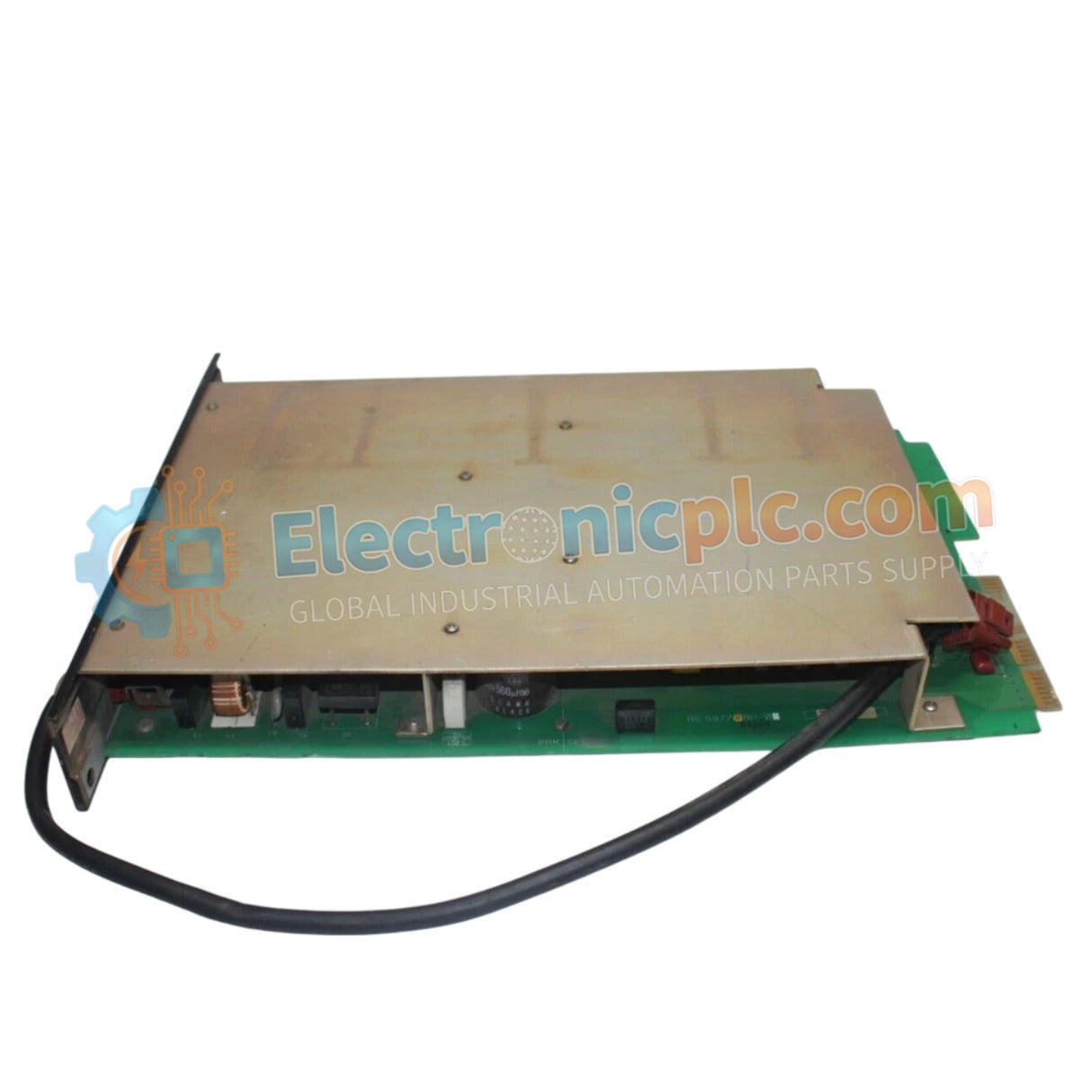
Configured for power distribution in industrial control platforms, the Yokogawa PS13*B (PS13*B Power Supply Module) provides direct physical/electrical execution of voltage regulation and system power delivery.
The PS13*B series utilizes a flexible suffix structure to designate specific input/output voltage configurations and power output capacities. Consult the system hardware manual to match the specific model suffix with the required backplane power load and input voltage source.
| Parameter | Specification |
|---|---|
| Model | PS13*B |
| Brand | Yokogawa |
| Origin | Japan |
| Weight | Standard industrial PSU form factor |
| Dimensions | Industrial cabinet mount dimensions |
| Operating Temp | Industrial grade (consult system manual) |
| Power Consumption | Refer to load capacity |
| Input/Output | Regulated DC voltage delivery |
The module functions as a primary DC power source, providing stable voltage regulation to the backplane bus and connected I/O hardware. To ensure long-term operational consistency, the unit incorporates internal surge protection and output filtering to mitigate electrical noise generated by upstream power grid fluctuations. The modular design enables efficient heat dissipation, supporting continuous operation under the varying electrical loads typically encountered in process control cabinets.
Q: Can multiple PS13*B modules be connected in parallel for current sharing?
A: Parallel operation is subject to the specific backplane design and module revision. Verify the system technical documentation to determine if the hardware supports active current sharing or if blocking diodes are required to prevent back-feeding between units.
Q: How is the thermal load managed during high-demand periods?
A: The module relies on passive convection cooling within the cabinet. Ensure that the specified installation clearances are maintained to prevent thermal accumulation and premature degradation of internal components.


