My Cart
0 items
Genuine Automation Parts | Worldwide Express Delivery | 12-Month Warranty — [GET A QUOTE]

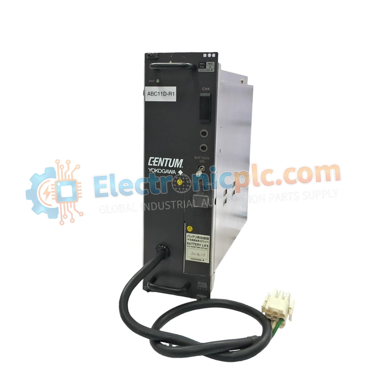
The YOKOGAWA PW301 S3, also cataloged as the PW301 S3 Power Module, operates as a dedicated hardware component for power regulation within DCS process control platforms.
| Parameter | Specification |
| Model | PW301 S3 |
| Brand | YOKOGAWA |
| Weight | 3.3 kg |
| Dimensions | 27.9 cm x 10.2 cm x 27.9 cm |
| Operating Temp | Standard industrial ambient range |
| Power Consumption | Load dependent |
The module integrates specialized circuitry for channel-to-channel isolation and voltage regulation required for DCS instrumentation loops. To maintain consistent output performance, the power supply utilizes internal feedback mechanisms to compensate for input line fluctuations. The output architecture is designed to minimize ripple characteristics, facilitating stable operation for sensitive analog input and output modules within the YOKOGAWA ecosystem. Effective thermal management is required, necessitating adequate cabinet airflow to prevent component derating during continuous operation in high-density rack configurations.
Q: What are the primary considerations when integrating this power supply into an existing rack?
A: Ensure that the module is fully seated into the backplane connector to guarantee proper electrical contact for power distribution. Mechanical retention latches must be locked to maintain structural stability and chassis ground continuity.
Q: How is thermal dissipation handled for this module?
A: The module relies on effective convection. Ensure a minimum clearance of 50 mm around the top and bottom of the unit to facilitate airflow and maintain operating temperature within defined limits.