My Cart
0 items
Genuine Automation Parts | Worldwide Express Delivery | 12-Month Warranty — [GET A QUOTE]

The YOKOGAWA PW302-S4, also cataloged as the PW302 Power Supply Module, operates as a dedicated hardware component for power distribution within Yokogawa DCS platforms. Configured to accept high-voltage AC inputs,...
Availability: Low stock: 99 left
Reliable Worldwide Delivery
30-Day Money-Back Guarantee
Need more details? Read our fullShipping PolicyandRefund Policy.


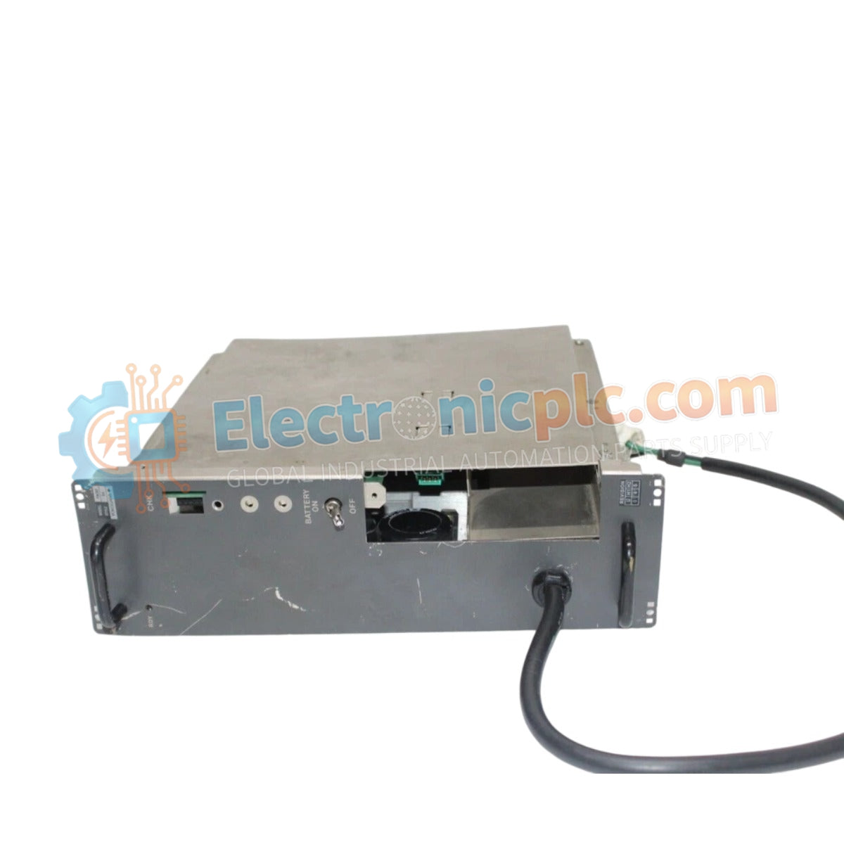
The YOKOGAWA PW302-S4, also cataloged as the PW302 Power Supply Module, operates as a dedicated hardware component for power distribution within Yokogawa DCS platforms. Configured to accept high-voltage AC inputs, this module regulates and stabilizes the electrical potential required for system backplane operations and associated logic circuitry.
The model identifier PW302-S4 signifies a specialized power supply configuration designed for 220-240 VAC input ranges. The "S4" suffix denotes a specific revision of the internal transformer and regulation circuitry tailored for regional power grid standards, ensuring compatibility with standard industrial control cabinets.
| Parameter | Specification |
|---|---|
| Model | PW302-S4 |
| Brand | Yokogawa |
| Origin | Japan |
| Weight | 3.6 kg |
| Dimensions | 10.2 cm x 27.9 cm x 25.4 cm |
| Operating Temp | 0 deg C to 50 deg C |
| Power Consumption | 220-240 VAC input |
The PW302-S4 is engineered to maintain voltage stability across the control bus, incorporating channel-to-channel isolation to mitigate the impact of common-mode electrical noise. The architecture supports the requirements of the 4-20 mA HART loop protocol by minimizing ripple current and ensuring a clean DC rail. Internal cold junction compensation (CJC) circuitry is managed within the integrated thermal distribution layout to preserve accuracy for high-density I/O configurations.
Q: Does the PW302-S4 allow for redundant power supply configurations?
A: Yes, this module supports load-sharing configurations when installed in redundant pairs within a compatible Yokogawa chassis. Ensure that the backplane diodes are functional to prevent reverse current flow between modules during load switching.
Q: What is the recommended clearance for thermal dissipation given the unit's power rating?
A: Maintain a minimum of 5 cm of clear space above and below the module to allow for natural convection airflow. Avoid installing the module in proximity to high-heat sources to ensure the internal components operate within the specified temperature range.


