My Cart
0 items
Genuine Automation Parts | Worldwide Express Delivery | 12-Month Warranty — [GET A QUOTE]

The YOKOGAWA PW302 S9884AT-02, also cataloged as the PW302 Power Module, operates as a dedicated hardware component for power regulation within Yokogawa DCS and PLC control environments. This module executes...
Availability: Low stock: 99 left
Reliable Worldwide Delivery
30-Day Money-Back Guarantee
Need more details? Read our fullShipping PolicyandRefund Policy.
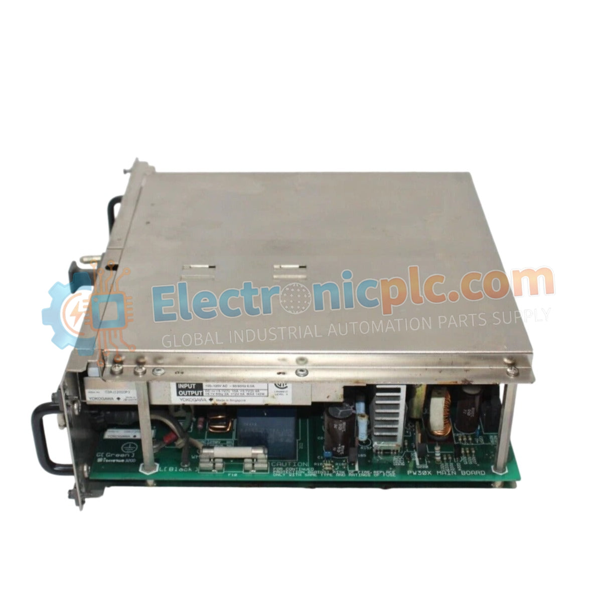

The YOKOGAWA PW302 S9884AT-02, also cataloged as the PW302 Power Module, operates as a dedicated hardware component for power regulation within Yokogawa DCS and PLC control environments. This module executes the conversion of incoming AC supply voltage into regulated DC power, maintaining the operational voltage rails required for system backplane logic and associated process instrumentation.
The model identifier PW302 S9884AT-02 indicates a specialized configuration. The "S9884AT-02" suffix denotes a specific revision level of the internal circuitry and mechanical interface, ensuring compatibility with updated backplane requirements in legacy and active Yokogawa control environments.
| Parameter | Specification |
|---|---|
| Model | PW302 S9884AT-02 |
| Brand | Yokogawa |
| Origin | Japan |
| Weight | 3.5 kg |
| Dimensions | 10.2 cm x 27.9 cm x 27.9 cm |
| Operating Temp | 0 deg C to 50 deg C |
| Power Consumption | Load dependent |
The PW302 S9884AT-02 ensures consistent voltage delivery, which is necessary to maintain the integrity of the 4-20 mA HART loop protocol across the control environment. The unit features channel-to-channel isolation to prevent the propagation of common-mode electrical noise or ground loops between control segments. Additionally, the internal thermal management system facilitates cold junction compensation (CJC), providing the electrical stability required for high-precision process measurement and control tasks.
Q: Does the PW302 S9884AT-02 support redundant power supply configurations?
A: Yes, this module supports parallel operation within a redundant power supply chassis. The internal bus circuitry is designed to manage automatic load balancing and failover, provided that both modules are connected to independent power input lines.
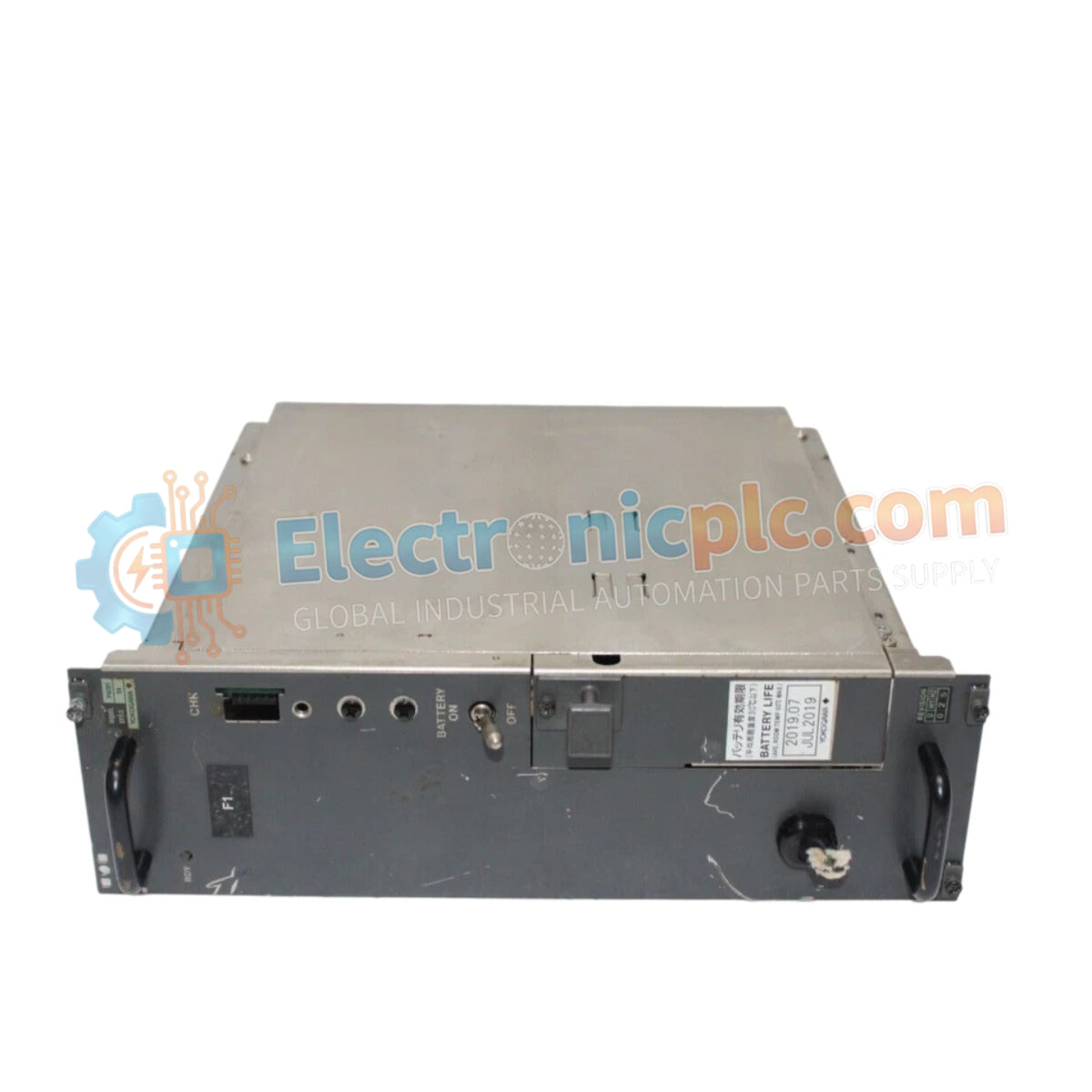
Q: How can I verify that the module is operating within nominal parameters?
A: Monitor the status LEDs on the front panel and verify the DC output voltage at the backplane test points using a calibrated multimeter. Any deviation from the nominal output voltage under load may indicate internal component degradation.


