My Cart
0 items
Genuine Automation Parts | Worldwide Express Delivery | 12-Month Warranty — [GET A QUOTE]

The YOKOGAWA PW401 S4, also cataloged as the PW401 Power Supply Module, operates as a dedicated hardware component for power distribution within Yokogawa DCS platforms. This module executes the conversion...
Availability: Low stock: 99 left
Reliable Worldwide Delivery
30-Day Money-Back Guarantee
Need more details? Read our fullShipping PolicyandRefund Policy.


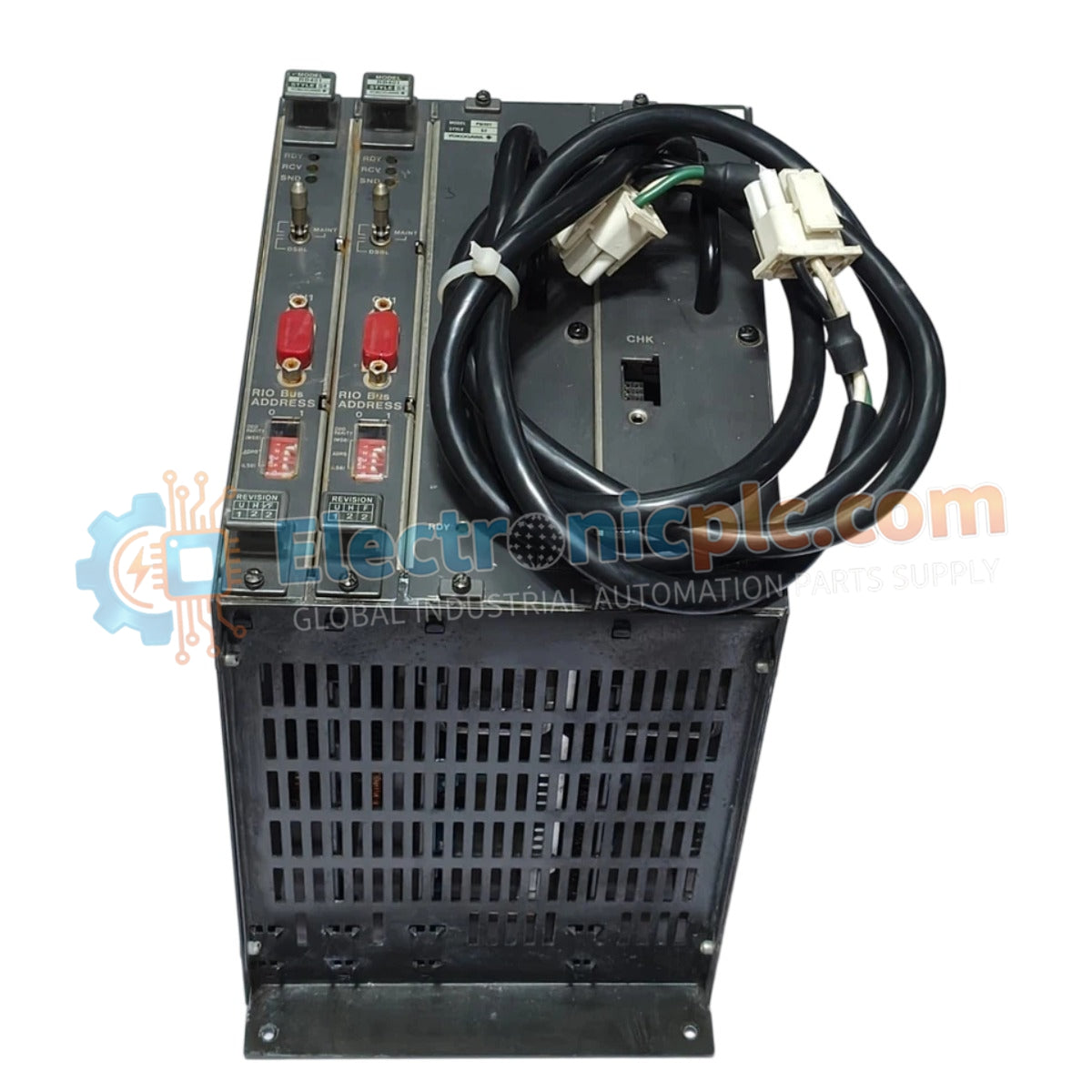
The YOKOGAWA PW401 S4, also cataloged as the PW401 Power Supply Module, operates as a dedicated hardware component for power distribution within Yokogawa DCS platforms. This module executes the conversion of 100-120 VAC input power into a stabilized 5.1 VDC output, maintaining the operational voltage rails required for system backplane logic and associated instrumentation.
The model identifier PW401 S4 denotes the specific hardware configuration. The "S4" suffix indicates a revised revision optimized for integration with high-density Yokogawa DCS chassis backplanes, ensuring mechanical alignment and electrical compatibility with the system's primary power distribution bus.
| Parameter | Specification |
|---|---|
| Model | PW401 S4 |
| Brand | Yokogawa |
| Origin | Japan |
| Weight | 2.0 kg |
| Dimensions | 5.1 cm x 20.3 cm x 20.3 cm |
| Input Voltage | 100-120 VAC, 50/60 Hz |
| Output Voltage | 5.1 VDC |
| Output Current | 20 A |
| Output Power | 102 W |
The PW401 S4 ensures consistent voltage delivery, which is necessary to maintain the integrity of the 4-20 mA HART loop protocol across the DCS environment. The unit features channel-to-channel isolation to prevent the propagation of common-mode electrical noise or ground loops between control segments. Additionally, the internal thermal management system facilitates cold junction compensation (CJC), providing the electrical stability required for high-precision process measurement and control tasks.
Q: Can the PW401 S4 be configured for redundant power operation?
A: Yes, this module supports parallel operation within a redundant power supply chassis. The internal bus circuitry is designed to manage automatic load balancing and failover, provided that both modules are connected to independent power input lines.
Q: Are there specific installation requirements to prevent overheating?
A: The PW401 S4 requires adequate vertical clearance to facilitate natural convection airflow. Ensure that no cabling obstructs the front-facing vent panels and that the ambient temperature remains within the specified operating range to prevent internal capacitor degradation.


