My Cart
0 items
Genuine Automation Parts | Worldwide Express Delivery | 12-Month Warranty — [GET A QUOTE]

Configured for power regulation and distribution in DCS platforms, the YOKOGAWA PW481-10 (PW481-10 Power Supply Module) provides direct physical/electrical execution. This module is engineered to convert incoming supply voltage into...
Availability: Low stock: 99 left
Reliable Worldwide Delivery
30-Day Money-Back Guarantee
Need more details? Read our fullShipping PolicyandRefund Policy.


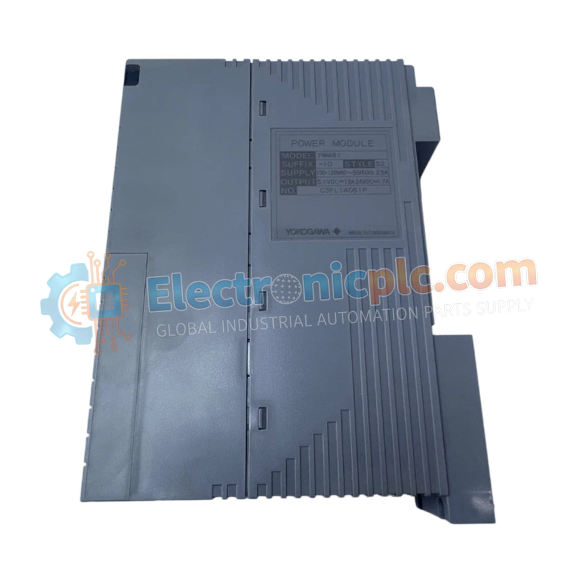
Configured for power regulation and distribution in DCS platforms, the YOKOGAWA PW481-10 (PW481-10 Power Supply Module) provides direct physical/electrical execution. This module is engineered to convert incoming supply voltage into regulated DC output, maintaining operational stability for connected control cards and field instrumentation within the Yokogawa DCS architecture.
| Parameter | Specification |
|---|---|
| Model | PW481-10 |
| Brand | Yokogawa |
| Origin | USA |
| Weight | 0.9 kg |
| Dimensions | 5.1 cm x 20.3 cm x 15.2 cm |
| Operating Temp | -10 deg C to 60 deg C |
| Power Consumption | Dependent on system load |
The PW481-10 facilitates stable voltage rails necessary for process control stability. The unit incorporates channel-to-channel isolation to prevent ground loops and electrical noise injection into the control bus. Consistent voltage delivery is maintained across varying load conditions to ensure the integrity of the 4-20 mA HART loop protocol utilized by downstream instrumentation. Cold junction compensation (CJC) and precise thermal management are implemented within the power stage to maintain performance accuracy across the operational temperature range.
Q: Does the PW481-10 support field hot-swapping during active system operation?
A: Hot-swapping depends on the specific backplane and DCS chassis configuration. Consult the system integration manual to verify if the rack backplane supports power module extraction without triggering a processor reset.
Q: What are the primary indicators of a power failure on this module?
A: The module front panel typically features status LEDs. Verify that the output voltage is within nominal parameters using a calibrated multimeter across the output terminals if the status light indicates a fault.


