My Cart
0 items
Genuine Automation Parts | Worldwide Express Delivery | 12-Month Warranty — [GET A QUOTE]

The YOKOGAWA PW481, also cataloged as the PW481 Power Supply Module, operates as a dedicated hardware component for power distribution within Yokogawa FCU, FIO Node Unit, and Optical ESB Bus...
Availability: Low stock: 99 left
Reliable Worldwide Delivery
30-Day Money-Back Guarantee
Need more details? Read our fullShipping PolicyandRefund Policy.


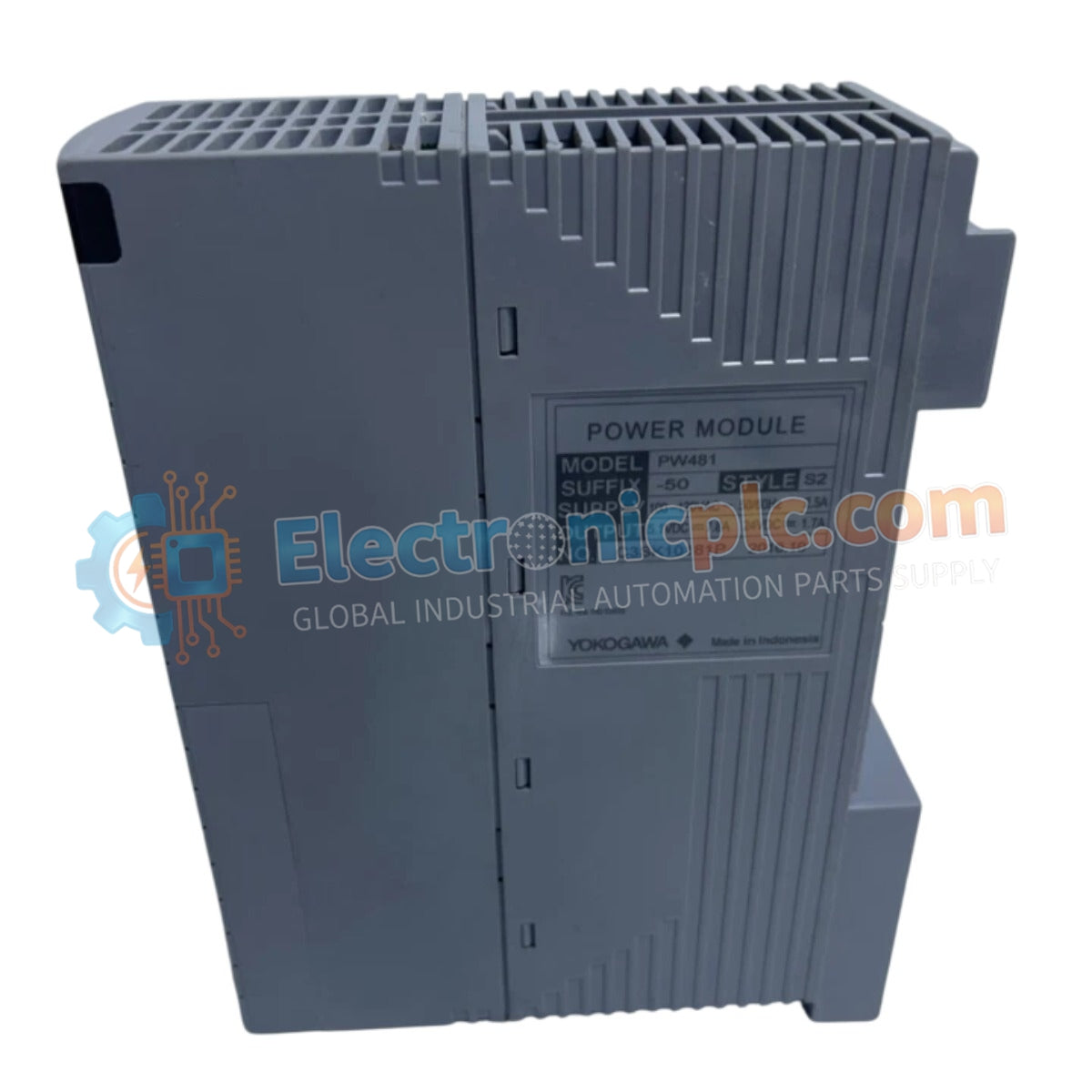
The YOKOGAWA PW481, also cataloged as the PW481 Power Supply Module, operates as a dedicated hardware component for power distribution within Yokogawa FCU, FIO Node Unit, and Optical ESB Bus Repeater Unit platforms. This module is exclusively engineered to provide system-specific voltage regulation for these control nodes and cannot be utilized as a generic power supply.
The model identifier PW481 utilizes suffix codes to define the environmental and safety protection specifications of the unit:
| Parameter | Specification |
|---|---|
| Model | PW481 |
| Brand | Yokogawa |
| Origin | Japan |
| Weight | 1.0 kg |
| Input Voltage | 100–120 VAC (+/- 10%) |
| Input Frequency | 50/60 Hz (+/- 3 Hz) |
| Power Consumption | 200 VA (max) |
| Operating Temp | Standard or -20 deg C to 70 deg C (G3 option) |
The PW481 is designed to maintain precise voltage rails across the backplane of connected Yokogawa control units. The module integrates channel-to-channel isolation to suppress electromagnetic interference within the ESB bus architecture. Its design ensures operational continuity for the FCU and FIO Node units by mitigating line transients. Cold junction compensation (CJC) and thermal management are strictly aligned with the requirements of the host control hardware to maintain system-wide synchronization.
Q: Can the PW481 be used as a standalone 24 VDC or 5 VDC power supply?
A: No. The PW481 is an exclusive power module specifically tailored for Yokogawa FCU, FIO Node Units, and Optical ESB Bus Repeater Units. It does not provide standard voltage outputs for third-party devices.
Q: What are the installation requirements for the G3 option version?
A: The G3 option is designed for corrosive environments and provides an extended operating temperature range. Ensure the chassis installation follows the standards outlined in the official Installation Guidance (TI 33J01J10-01JA) to ensure environmental sealing and thermal dissipation.


