My Cart
0 items
Genuine Automation Parts | Worldwide Express Delivery | 12-Month Warranty — [GET A QUOTE]

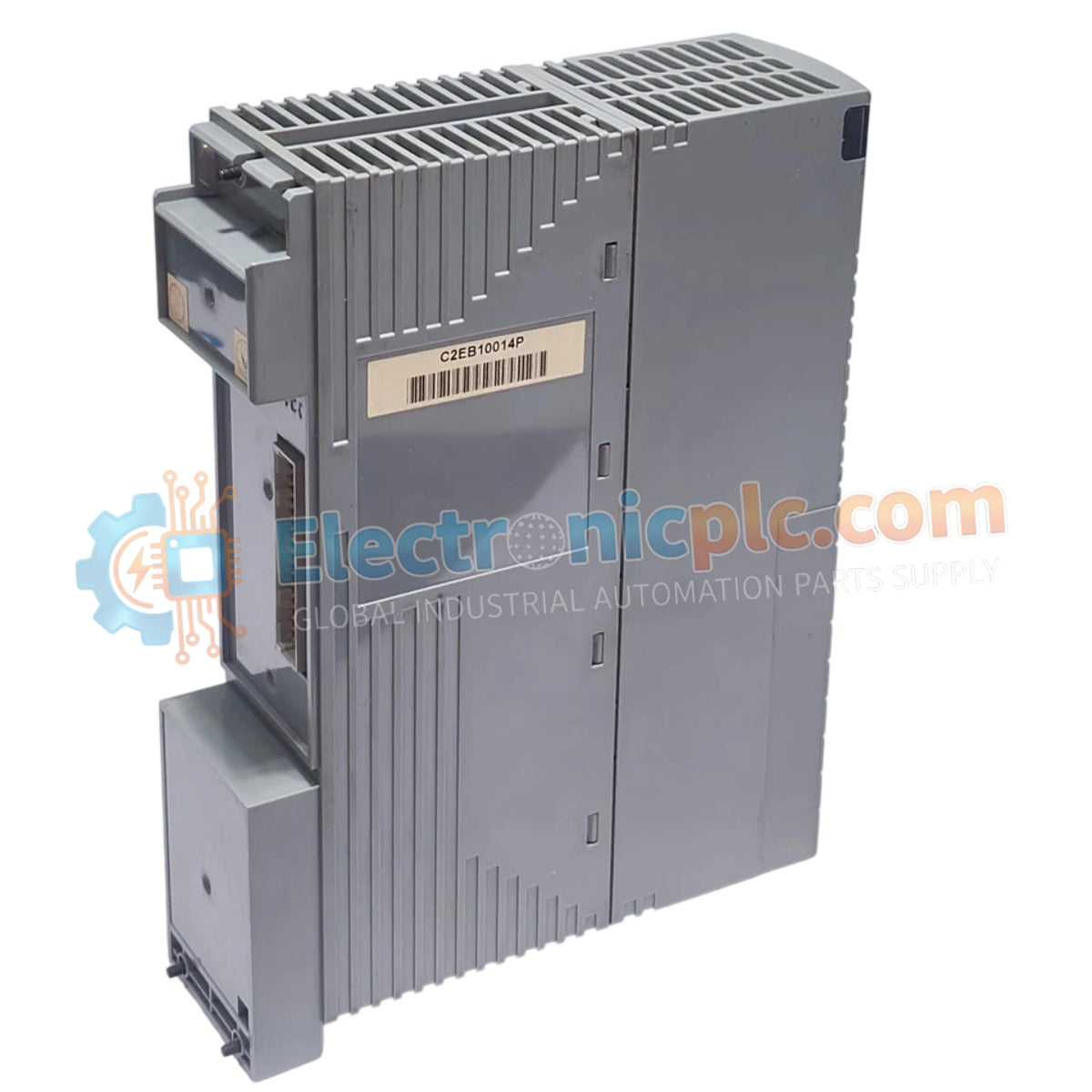
Configured for power conversion in DCS process control platforms, the YOKOGAWA PW482-10 S2 (PW482-10 Power Supply Module) provides direct physical/electrical execution.
Availability: Low stock: 99 left
Reliable Worldwide Delivery
30-Day Money-Back Guarantee
Need more details? Read our fullShipping PolicyandRefund Policy.


Configured for power conversion in DCS process control platforms, the YOKOGAWA PW482-10 S2 (PW482-10 Power Supply Module) provides direct physical/electrical execution.
| Parameter | Specification |
| Model | PW482-10 S2 |
| Brand | YOKOGAWA |
| Origin | Subject to factory batch |
| Weight | 0.9 kg |
| Dimensions | 5.1 cm x 20.3 cm x 15.2 cm |
| Operating Temp | -20 deg C to +70 deg C |
| Power Consumption | Load dependent |
| Input Voltage | 100-120 VAC / 220-240 VAC |
| Output Voltage | 24 VDC (S2 variant) |
The module integrates specialized circuitry for channel-to-channel isolation and voltage regulation required in DCS instrumentation loops. To maintain consistent output performance, the power supply utilizes internal feedback mechanisms to compensate for input line fluctuations. The output architecture is designed to minimize ripple characteristics, facilitating stable operation for sensitive analog input and output modules within the YOKOGAWA ecosystem. Effective thermal management is required across the extended operating range of -20 deg C to +70 deg C, necessitating adequate cabinet airflow to prevent component derating during continuous operation in high-density rack configurations.
Q: Are there specific requirements for the input voltage selection?
A: The input stage supports dual-range operation. Users must verify the specific jumper or switch setting (if applicable) or confirm the factory-configured input range matches the site supply (100-120 VAC or 220-240 VAC) prior to commissioning to prevent damage.
Q: How does the S2 variant differ in power distribution compared to the standard model?
A: The PW482-10 S2 is optimized for a single-rail 24 VDC output. Unlike the standard PW482-10, which provides split +12 VDC and +24 VDC rails for high-power distribution, the S2 variant is intended for applications where a dedicated, lower-current 24 VDC source is sufficient.


