My Cart
0 items
Genuine Automation Parts | Worldwide Express Delivery | 12-Month Warranty — [GET A QUOTE]

The YOKOGAWA PW484-10 S1, also cataloged as the PW484-10 Power Supply Module, operates as a dedicated hardware component for high-capacity power regulation within Yokogawa DCS platforms. This module executes the...
Availability: Low stock: 99 left
Reliable Worldwide Delivery
30-Day Money-Back Guarantee
Need more details? Read our fullShipping PolicyandRefund Policy.


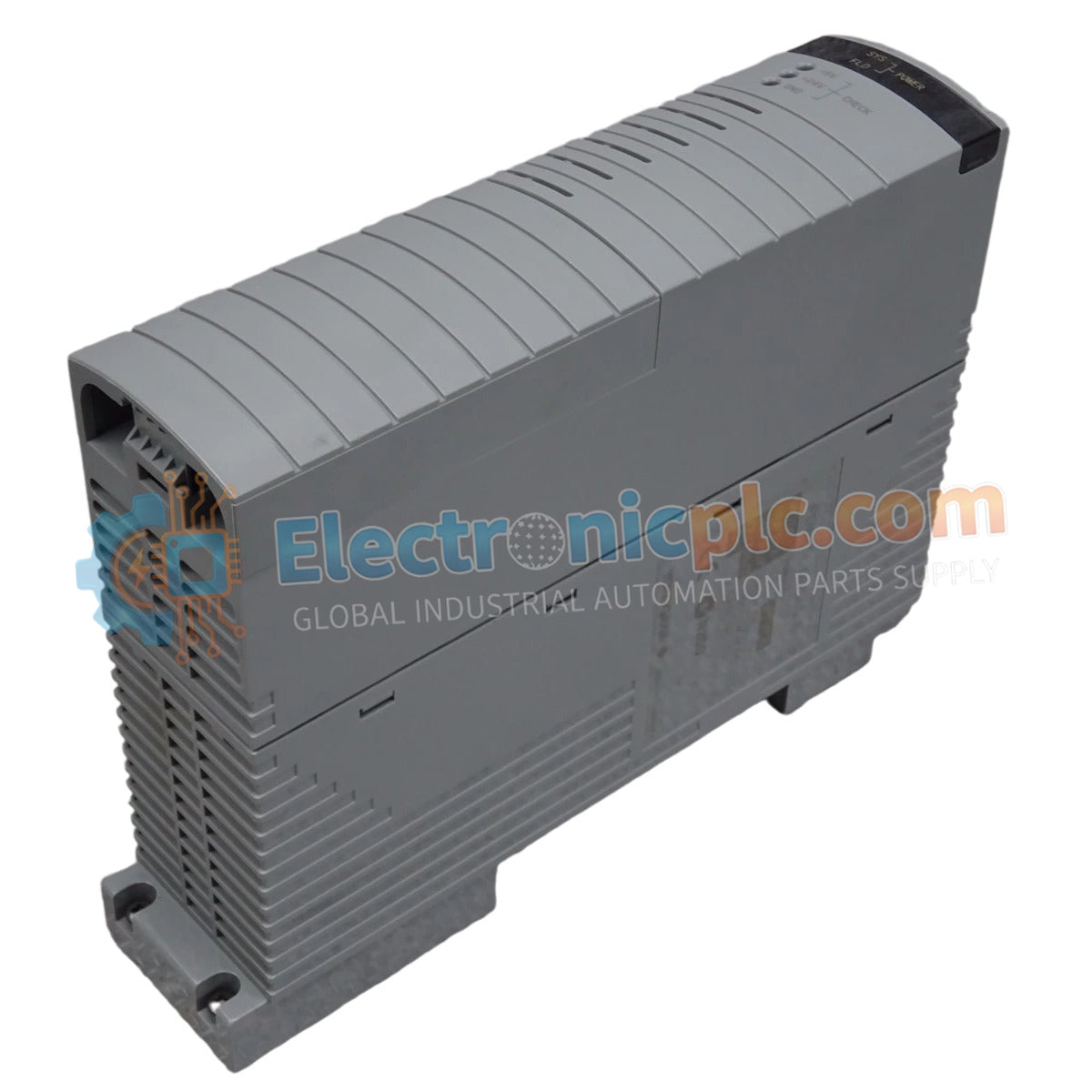
The YOKOGAWA PW484-10 S1, also cataloged as the PW484-10 Power Supply Module, operates as a dedicated hardware component for high-capacity power regulation within Yokogawa DCS platforms. This module executes the conversion of incoming AC supply voltages into regulated DC power, maintaining the operational voltage rails required for system backplane logic and associated instrumentation.
The model identifier PW484-10 S1 denotes the specific hardware configuration and revision level. The "S1" suffix indicates a revision optimized for integration with standard Yokogawa DCS chassis backplanes, ensuring mechanical alignment and electrical compatibility with the system's power distribution bus.
| Parameter | Specification |
|---|---|
| Model | PW484-10 S1 |
| Brand | Yokogawa |
| Origin | Japan |
| Weight | 1.1 kg |
| Dimensions | 5.1 cm x 20.3 cm x 15.2 cm |
| Operating Temp | 0 deg C to 50 deg C |
| Power Consumption | System load dependent |
The PW484-10 S1 ensures consistent voltage delivery, which is necessary to maintain the integrity of the 4-20 mA HART loop protocol across the DCS environment. The unit features channel-to-channel isolation to prevent the propagation of common-mode electrical noise or ground loops. Additionally, the internal thermal management system facilitates cold junction compensation (CJC), providing the electrical stability required for high-precision process measurement and control tasks.
Q: Can the PW484-10 S1 be configured for N+1 redundancy?
A: Yes, the module supports parallel operation within a redundant power supply chassis. The internal bus circuitry is designed to manage automatic load balancing and failover, provided that both modules are connected to independent power input lines.
Q: Are there specific limitations when performing live maintenance or hot-swapping?
A: The module is designed for hot-swapping within supported backplanes. However, operators must ensure that the rack is not operating at maximum thermal capacity before removal, and verify that the chassis locking pins are correctly engaged to prevent intermittent contact during the insertion sequence.


