My Cart
0 items
Genuine Automation Parts | Worldwide Express Delivery | 12-Month Warranty — [GET A QUOTE]

The YOKOGAWA PW501 Power Supply Module operates as a dedicated hardware component for power distribution within Yokogawa CENTUM CS and VP control systems. This module is engineered to provide a...
Availability: Low stock: 99 left
Reliable Worldwide Delivery
30-Day Money-Back Guarantee
Need more details? Read our fullShipping PolicyandRefund Policy.


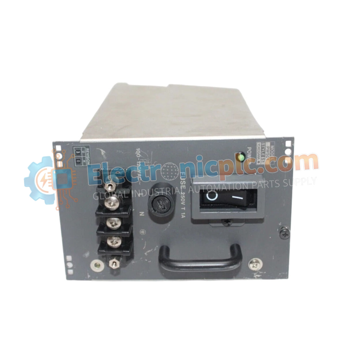
The YOKOGAWA PW501 Power Supply Module operates as a dedicated hardware component for power distribution within Yokogawa CENTUM CS and VP control systems. This module is engineered to provide a regulated 5 VDC output, supporting critical infrastructure such as optical repeater units and field control nodes. Its design ensures stable electrical distribution while maintaining high efficiency in industrial operating environments.
| Parameter | Specification |
|---|---|
| Model | PW501 |
| Brand | Yokogawa |
| Origin | Japan |
| Weight | 0.9 kg |
| Dimensions | 10.2 cm x 12.7 cm x 20.3 cm |
| Input Voltage | 100–120 VAC (+/- 10%) |
| Output Voltage | 5 VDC |
| Output Current | 5 A |
| Power Output | 25 W |
| Operating Temp | -10 deg C to 55 deg C |
The PW501 facilitates consistent voltage rails necessary for system-wide synchronization and control integrity. The module employs natural convection for cooling, eliminating the need for fans and reducing maintenance requirements. Channel-to-channel isolation is maintained to mitigate the impact of common-mode noise and ground loops across the DCS bus. Cold junction compensation (CJC) and thermal management are integrated into the module's architecture to ensure performance accuracy across the specified temperature range.
Q: Is the PW501 module suitable for use in high-vibration environments?
A: Yes, the rugged construction and secure DIN rail or panel-mount options provide stability in industrial conditions. Ensure all mounting screws are tightened to torque specifications to minimize mechanical stress on the backplane connectors.
Q: What is the benefit of the fanless design in this DCS application?
A: The fanless design utilizes natural convection, which minimizes dust ingress and mechanical failure points. This ensures long-term operational continuity for critical control systems where periodic fan replacement is not feasible.


