My Cart
0 items
Genuine Automation Parts | Worldwide Express Delivery | 12-Month Warranty — [GET A QUOTE]

The YOKOGAWA PW502 S1, also cataloged as the PW502 Power Supply Unit, operates as a dedicated hardware component for power regulation within Yokogawa process control platforms. Configured to manage incoming...
Availability: Low stock: 99 left
Reliable Worldwide Delivery
30-Day Money-Back Guarantee
Need more details? Read our fullShipping PolicyandRefund Policy.


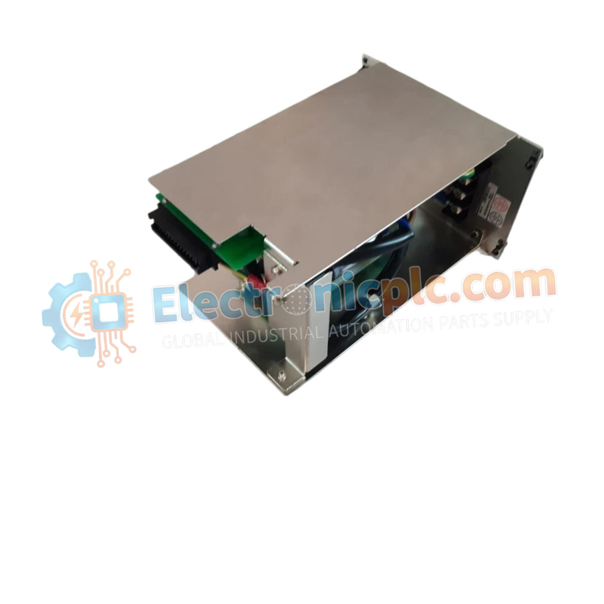
The YOKOGAWA PW502 S1, also cataloged as the PW502 Power Supply Unit, operates as a dedicated hardware component for power regulation within Yokogawa process control platforms. Configured to manage incoming AC line voltage, this unit converts input power into the regulated DC levels required for the operational stability of system backplanes and integrated control modules.
The model identifier PW502 S1 signifies a specific hardware iteration. The "S1" suffix indicates a revised board layout and component selection optimized for current-generation Yokogawa DCS chassis, ensuring mechanical form factor compatibility and standard electrical interface matching.
| Parameter | Specification |
|---|---|
| Model | PW502 S1 |
| Brand | Yokogawa |
| Origin | Japan |
| Weight | 3.5 kg |
| Dimensions | 2.5 cm x 12.7 cm x 20.3 cm |
| Operating Temp | 0 deg C to 50 deg C |
| Power Consumption | System load dependent |
The PW502 S1 is designed to maintain consistent voltage rails necessary for the continuity of the 4-20 mA HART loop protocol. The module incorporates channel-to-channel isolation to prevent the injection of common-mode electrical noise into the control bus. Integrated cold junction compensation (CJC) is maintained within the power stage, ensuring that thermal variances do not interfere with the precision of field instrumentation signals.
Q: Can the PW502 S1 be operated in a redundant power configuration?
A: Yes, this module is compatible with redundant power supply backplanes. When paired with a secondary unit, the system manages automatic load sharing and failover to ensure that no interruption in power occurs if a single module fails.
Q: What are the risks of exceeding the module's rated operating temperature?
A: Operating above 50 deg C significantly accelerates the degradation of internal electrolytic capacitors. This can lead to increased output ripple, voltage instability, and eventual premature module failure. Always ensure adequate rack airflow.


