Skip to product information
1 of 3

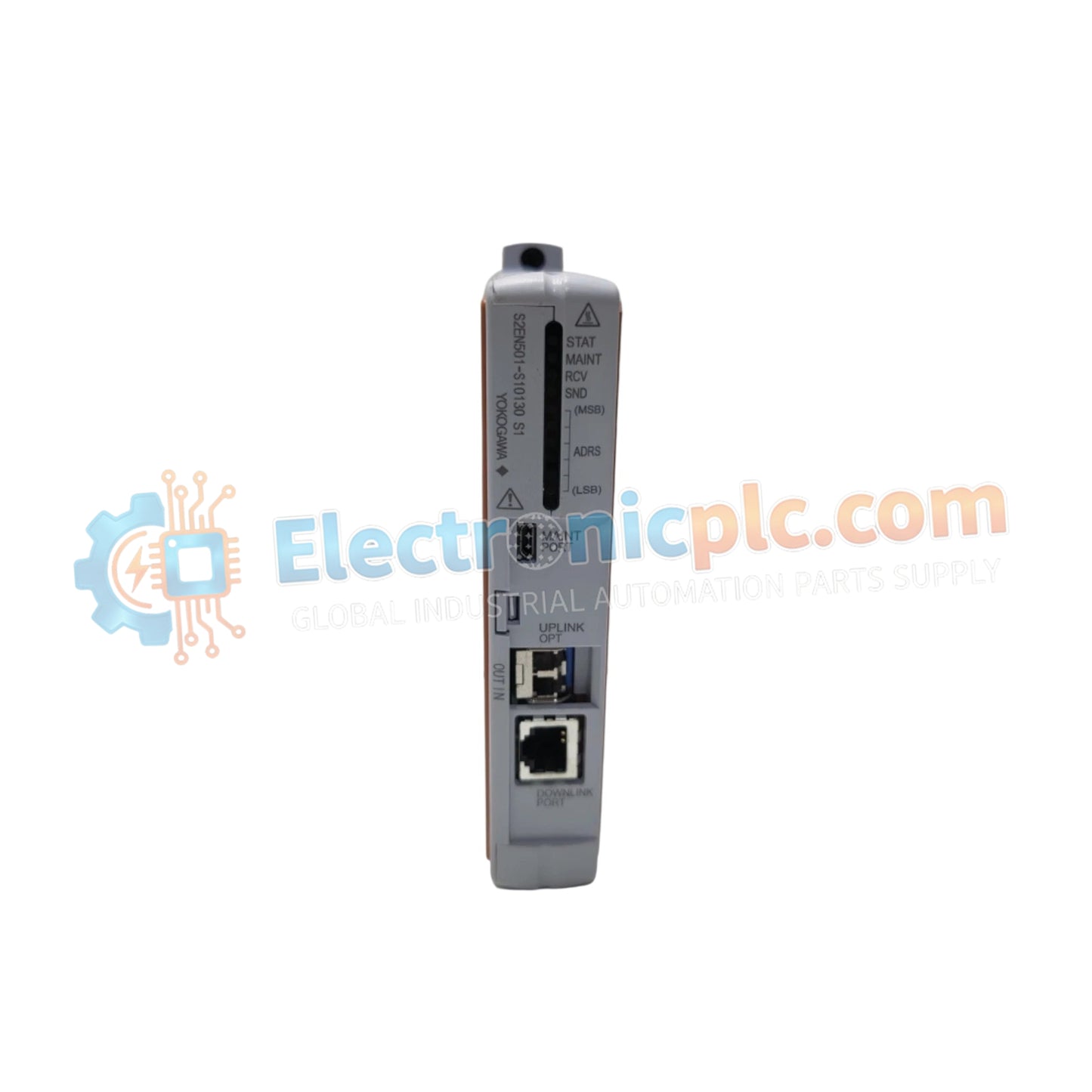
S2EN501-S00030 Optical ESB Bus Repeater Slave Module YOKOGAWA

S2EN501-S00030 Optical ESB Bus Repeater Slave Module YOKOGAWA

Configured for signal termination within the N-IO system platform, the YOKOGAWA A2SMX801-S000 (A2SMX801-S000 Terminal Board) provides direct physical execution of I/O signal distribution. The board serves as the primary interface...

28 people are viewing this right now

AvailabilityIn stock

SKU: S2EN501-S00030
Vendor: Yokogawa

Shipping & Returns

Reliable Worldwide Delivery

  • Carriers: Shipped via DHL, FedEx, UPS, or USPS.
  • Dispatch: Orders processed in 1-2 business days and dispatched within 3-5 business days.
  • Tracking: Full tracking details provided via email upon shipment.

30-Day Money-Back Guarantee

  • Guarantee: 30-day return window for in-stock, factory-sealed products.
  • Condition: Items must be unopened, unused, and in original packaging.
  • Authenticity: We guarantee 100% original and authentic hardware.

Need more details? Read our fullShipping PolicyandRefund Policy.

Authenticity & Warranty

  • Genuine Guarantee: We supply only 100% original, brand-new, and factory-sealed industrial automation parts.
  • Full Coverage: Every component is backed by a 12-month comprehensive warranty from the date of purchase.
  • Traceability: All products come with original factory documentation and accessories for full industrial compliance.

Technical Support & Sourcing

  • Expert Assistance: Our technical team provides free consultation to help you verify compatibility for DCS and PLC systems.
  • Rare Part Sourcing: Specializing in obsolete and hard-to-find components from Allen-Bradley, Siemens, ABB, HIMA, and more.
  • Bulk Inquiries: Contact us at pambo@5gplc.com for volume pricing or customized project quotes.
View full product details

Configured for signal termination within the N-IO system platform, the YOKOGAWA A2SMX801-S000 (A2SMX801-S000 Terminal Board) provides direct physical execution of I/O signal distribution. The board serves as the primary interface to connect field instruments and sensors to the control system, facilitating data acquisition across N-IO modules without intermediate active signal conditioning.

Suffix Breakdown & Model Matrix

  • A2SMX801: Base model designation for the N-IO signal terminal board.
  • -S: Standard hardware configuration for general-purpose signal termination.
  • 000: Base revision level for standard I/O mapping and connector layout.

Hardware Specifications

Parameter Specification
Model A2SMX801-S000
Brand YOKOGAWA
Origin Japan
Weight 0.3 kg
Dimensions Standard N-IO footprint
Operating Temp 0 to 60 deg C
Power Consumption Passive (None)
Interface Type Field signal termination
Isolation Non-isolated

Channel-to-Channel Isolation and Field Connectivity

The A2SMX801-S000 functions as a non-isolated signal termination interface. It is engineered to maintain a low-impedance connection path between field transmitters and the N-IO backplane. Since this board lacks active galvanic isolation, it is designed for deployment in configurations where field loops are either inherently self-isolated or where grounding requirements are managed by external loop-level protection components. The board ensures consistent continuity for 4-20 mA HART loop protocol signals by minimizing insertion loss across the terminal points.

Frequently Asked Questions

Q: Does this terminal board require an external power supply for signal pass-through?

A: No. The A2SMX801-S000 is a passive termination component and does not require an auxiliary power supply to facilitate signal flow.

Q: Is this board compatible with both current and voltage input types?

A: Yes. The board serves as a physical interface for field wiring; however, the actual signal type conversion is determined by the specific N-IO module plugged into the associated baseplate.

Field Installation Guidelines

  1. Ensure the N-IO node is fully de-energized before mounting the board to prevent accidental shorts during terminal wiring.
  2. Align the board precisely with the baseplate connectors; ensure the mechanical fasteners are fully engaged to provide a stable electrical contact.
  3. Tighten all screw terminals to the torque specifications provided in the maintenance manual to prevent resistive heating and signal degradation.
  4. Separate field signal wiring from high-voltage AC cables within the cabinet to reduce induced electromagnetic noise in the non-isolated circuitry.
  5. Verify that the cable shield drain wires are connected to the cabinet's instrument ground bus at the entry point to maintain signal integrity.