My Cart
0 items
Genuine Automation Parts | Worldwide Express Delivery | 12-Month Warranty — [GET A QUOTE]

The YOKOGAWA S9841DA, also cataloged as the S9841DA I/O Module, operates as a dedicated hardware component for mixed-signal acquisition and digital control execution within YOKOGAWA PLC and DCS platforms.
Availability: Low stock: 99 left
Reliable Worldwide Delivery
30-Day Money-Back Guarantee
Need more details? Read our fullShipping PolicyandRefund Policy.

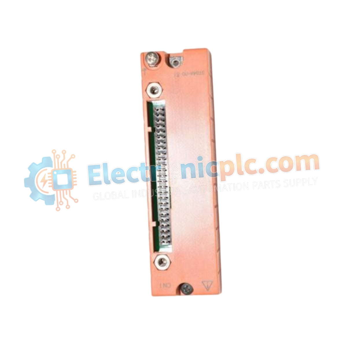
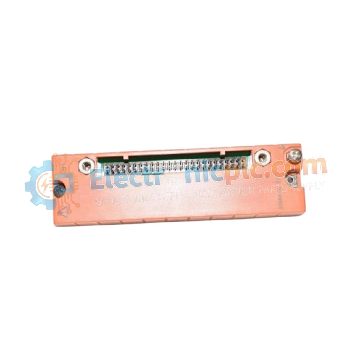
The YOKOGAWA S9841DA, also cataloged as the S9841DA I/O Module, operates as a dedicated hardware component for mixed-signal acquisition and digital control execution within YOKOGAWA PLC and DCS platforms.
| Parameter | Specification |
| Model | S9841DA |
| Brand | YOKOGAWA |
| Origin | Subject to factory batch |
| Weight | 0.3 kg |
| Operating Temp | -20 deg C to +60 deg C |
| Power Consumption | 2 W |
| Input Channels | 8 (Analog/Digital) |
| Output Channels | 8 (Digital) |
| Input Voltage Range | 0-24 VDC |
| Output Voltage Range | 24 VDC |
| Isolation Voltage | 1500 VAC |
| Response Time | < 1 ms |
The S9841DA provides high-speed data acquisition for industrial control loops. The module architecture incorporates 1500 VAC galvanic isolation between the field-side interface and the internal system backplane. This isolation prevents ground loops and electrical transients from propagating through the Yokogawa FA-M3 or CENTUM backplane during high-speed switching events. The input stages are configured for threshold detection of 0-24 VDC signals, ensuring deterministic response times of less than 1 ms, which is necessary for critical process interlocks.
Q: How does the S9841DA handle high-speed digital input filtering?
A: The module includes hardware-level debouncing filters to ignore transient contact bounce in mechanical switch inputs. The input response time of <1 ms is maintained through an optimized sampling clock, ensuring that digital state changes are registered within the controller's scan cycle.
Q: Is this module compatible with FA-M3 series backplanes?
A: Yes, the S9841DA is designed for integration within the FA-M3 rack system. Ensure that the module is assigned a valid base and slot address through the engineering software to correctly map the 8 analog/digital inputs and 8 digital outputs to the CPU's memory register space.


