
My Cart
0 items
Genuine Automation Parts | Worldwide Express Delivery | 12-Month Warranty — [GET A QUOTE]

Configured for high-density signal acquisition in industrial control platforms, the Yokogawa S9950DD-01 (S9950DD-01 Data Acquisition Module) provides direct physical/electrical execution of 16-channel analog signal processing and integration.
Availability: Low stock: 99 left
Reliable Worldwide Delivery
30-Day Money-Back Guarantee
Need more details? Read our fullShipping PolicyandRefund Policy.
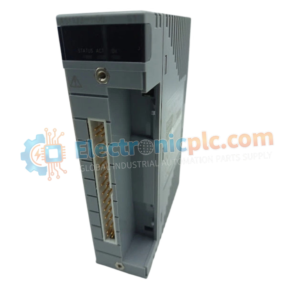
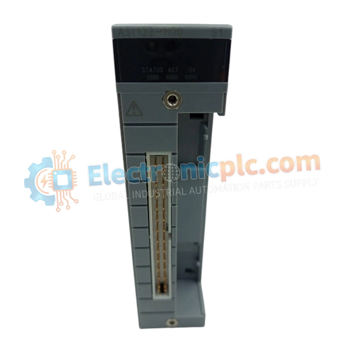
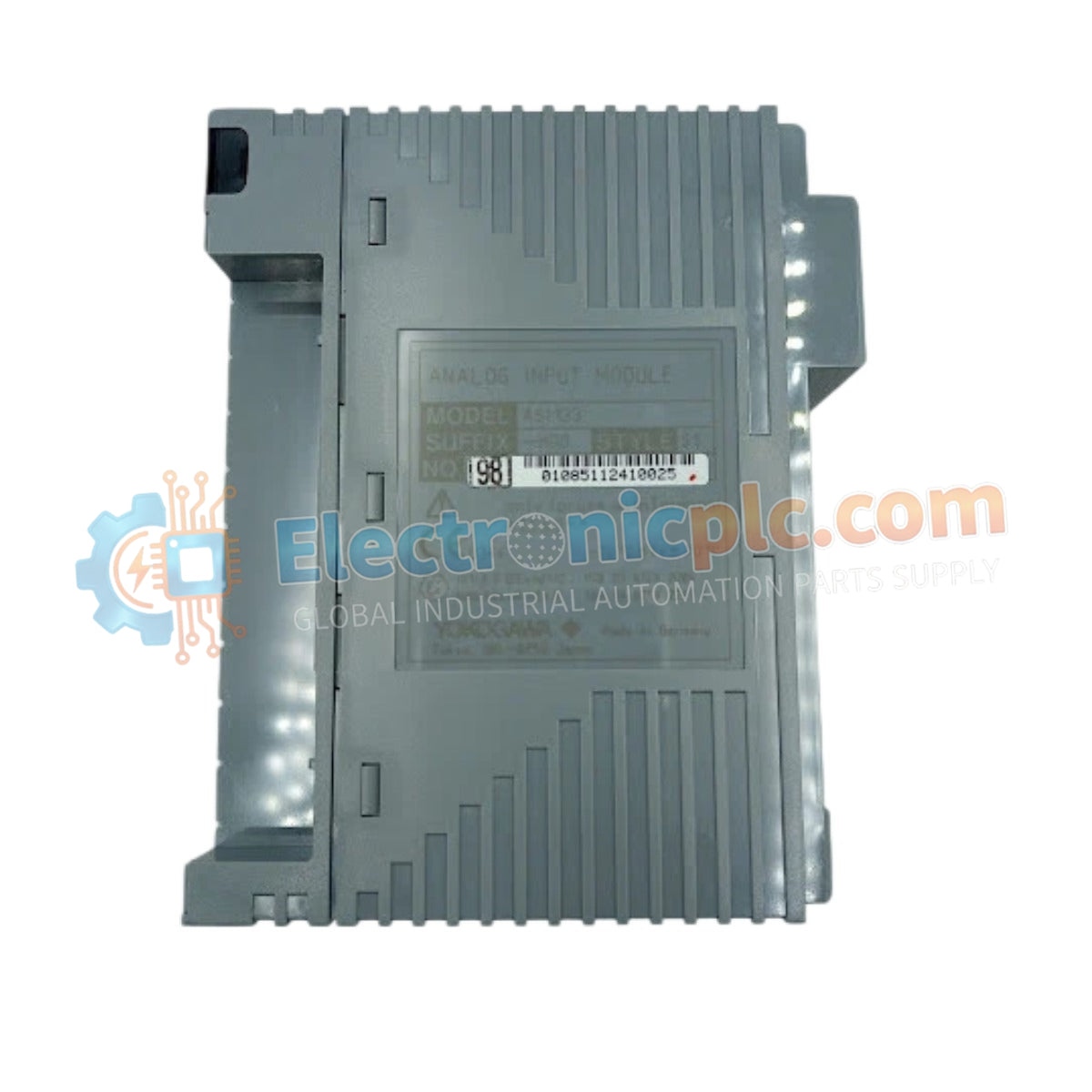
Configured for high-density signal acquisition in industrial control platforms, the Yokogawa S9950DD-01 (S9950DD-01 Data Acquisition Module) provides direct physical/electrical execution of 16-channel analog signal processing and integration.
| Parameter | Specification |
|---|---|
| Model | S9950DD-01 |
| Brand | Yokogawa |
| Origin | Japan |
| Weight | 0.2 kg |
| Dimensions | 10 cm x 10 cm x 10 cm |
| Operating Temp | Consult system environmental specifications |
| Power Consumption | Refer to backplane power budget |
| Channel Count | 16 |
| Sensor Compatibility | Universal analog input types |
The module acts as a high-precision interface for diverse industrial sensors, converting localized field signals into standardized digital data for controller logic. The architecture employs independent channel isolation, which is critical for suppressing common-mode electrical noise and preventing ground loops across the 16 available input paths. By decoupling the sensing circuitry from the system backplane, the module ensures that transient voltages on one field instrument do not impact the measurement accuracy or reliability of adjacent channels.
Q: Does the S9950DD-01 require specific hardware jumpers to define input ranges?
A: No, the module is designed for software-defined configuration. Signal types and scaling factors are set through the host system's engineering software to match the specific transducer or sensor output.
Q: Can this module be utilized in environments with high electromagnetic interference?
A: The integrated channel isolation and shielding interface are engineered to mitigate the effects of electromagnetic interference (EMI). However, best practices dictate that sensor cabling should be routed through shielded conduits, separated from high-voltage AC lines.


