My Cart
0 items
Genuine Automation Parts | Worldwide Express Delivery | 12-Month Warranty — [GET A QUOTE]

The YOKOGAWA SA53900, also cataloged as the SA-539-00 System Fault Alarm Module, operates as a dedicated hardware component for monitoring and annunciating system-level diagnostic errors within distributed control and PLC...
Availability: In stock
Reliable Worldwide Delivery
30-Day Money-Back Guarantee
Need more details? Read our fullShipping PolicyandRefund Policy.
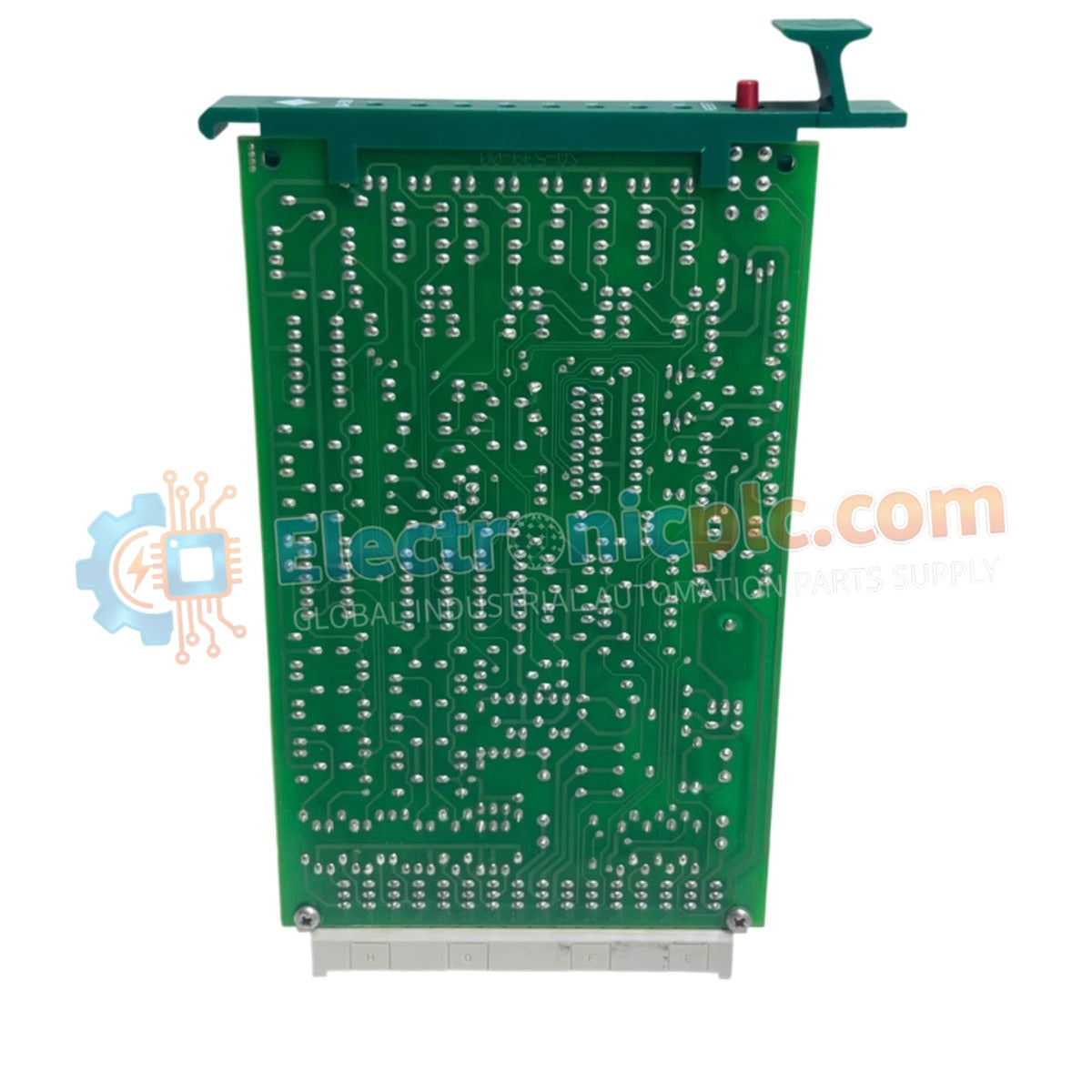

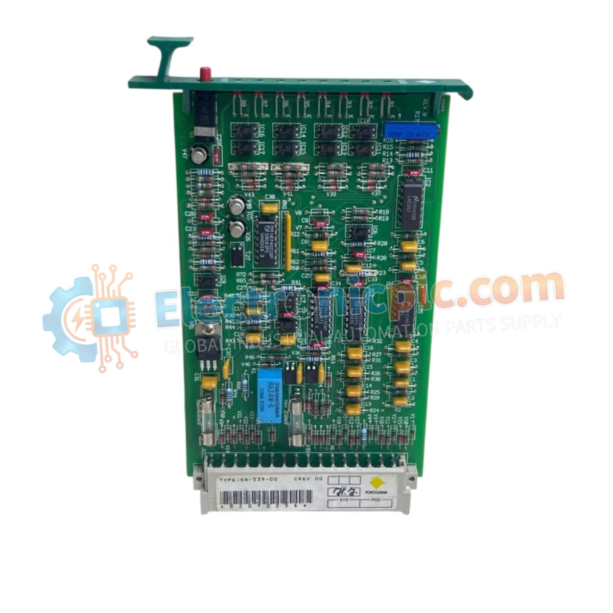
The YOKOGAWA SA53900, also cataloged as the SA-539-00 System Fault Alarm Module, operates as a dedicated hardware component for monitoring and annunciating system-level diagnostic errors within distributed control and PLC network architectures.
| Parameter | Specification |
|---|---|
| Model | SA53900 (SA-539-00) |
| Brand | YOKOGAWA |
| Origin | Japan |
| Weight | 0.11 kg (0.24 lbs) |
| Dimensions | Standard Yokogawa module form factor |
| Operating Temp | 0 deg C to 60 deg C |
| Power Consumption | 24 VDC nominal |
| Channels | 1 main channel with 8 sub-alarm inputs |
| Interface | LED status annunciation |
The SA53900 module is engineered to provide immediate visual and electrical feedback regarding system health. By integrating 8 sub-alarm inputs into a single managed channel, the module reduces the complexity of cabinet-level wiring while ensuring that critical faults are registered by the control system logic. The inclusion of front-panel LED indicators is required for rapid diagnostic verification by field maintenance personnel, allowing for immediate identification of fault conditions without needing to access the control system software.
Q: Does the SA53900 require external wiring for the 8 sub-alarm inputs?
A: Yes. Each sub-alarm input must be wired from the corresponding system component (e.g., power supply fault relays or chassis temperature sensors) to the module terminals to facilitate centralized fault monitoring.
Q: Is the SA53900 compatible with older Yokogawa control systems?
A: The module is designed for legacy system architectures. Ensure that the backplane voltage and communication protocols are compatible with the specific revision of the control rack before installation.


