
My Cart
0 items
Genuine Automation Parts | Worldwide Express Delivery | 12-Month Warranty — [GET A QUOTE]

The Yokogawa SNB10D-415/CU2N, also cataloged as the SNB10D-415 Safety Node Unit, operates as a dedicated hardware component for field signal interface and power distribution within ProSafe-RS Safety Instrumented System (SIS)...
Availability: In stock
Reliable Worldwide Delivery
30-Day Money-Back Guarantee
Need more details? Read our fullShipping PolicyandRefund Policy.

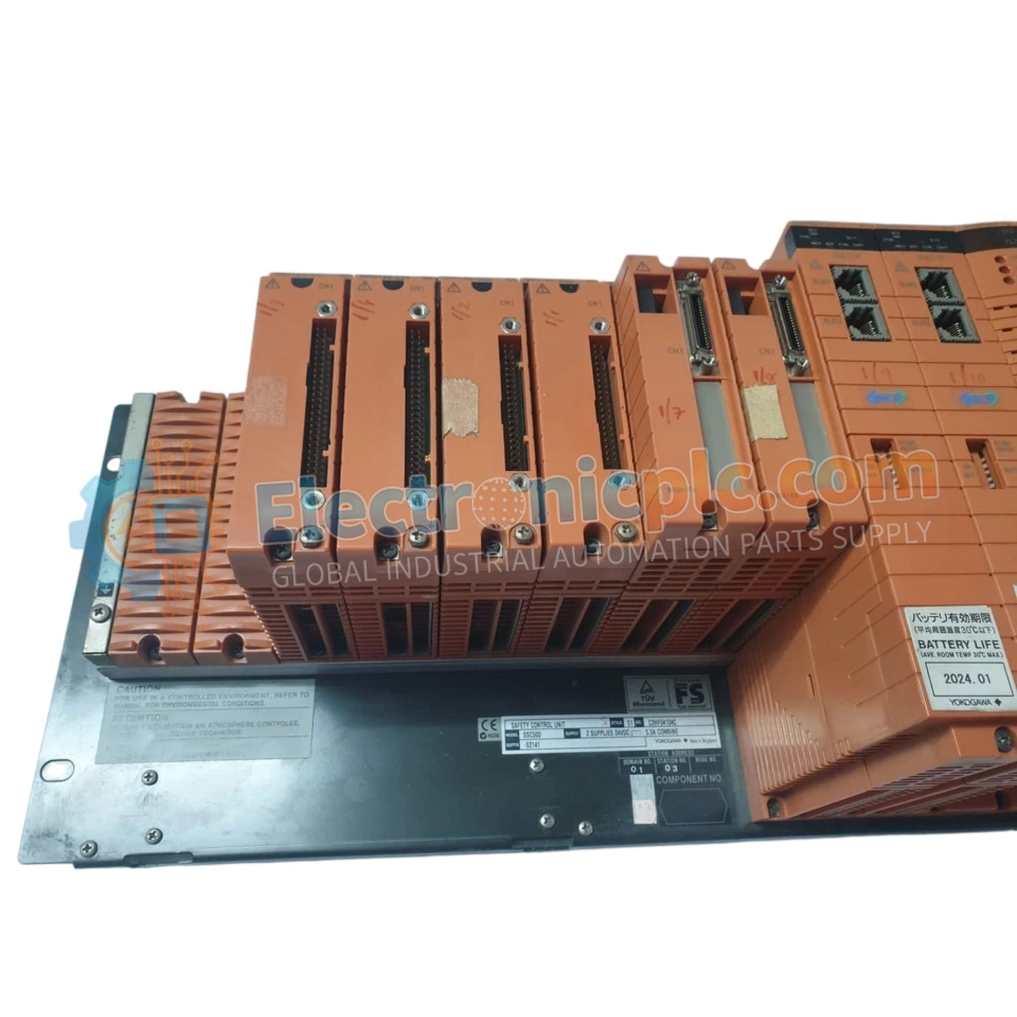
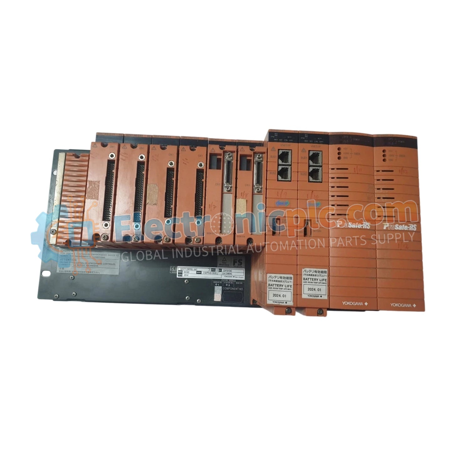
The Yokogawa SNB10D-415/CU2N, also cataloged as the SNB10D-415 Safety Node Unit, operates as a dedicated hardware component for field signal interface and power distribution within ProSafe-RS Safety Instrumented System (SIS) platforms.
| Parameter | Specification |
|---|---|
| Model | SNB10D-415/CU2N |
| Brand | Yokogawa |
| Origin | Japan |
| Weight | 5.9 kg |
| Dimensions | 482.6 mm x 221.5 mm x 205 mm |
| Operating Temp | -10 to 55 deg C |
| Power Consumption | Supported via redundant DC supply |
| Safety Standard | SIL3 compliant (IEC 61508) |
| Mounting | Rack-mounted |
The SNB10D-415 utilizes a dual-redundant design to maintain signal availability in safety-critical loops, satisfying SIL3 functional safety requirements. By facilitating the interface between field instrumentation and the safety controller, the node unit provides consistent electrical isolation and power regulation for I/O modules. In the event of a primary power or signal path degradation, the redundant architecture enables seamless transition to secondary circuits, ensuring that fail-safe state execution remains uninterrupted. The node is engineered to minimize crosstalk and signal degradation, which is necessary for maintaining loop integrity in industrial process environments.
Q: Does the dual-redundant design support hot-swapping of I/O modules while the node is powered?
A: Yes. The SNB10D-415 architecture allows for the hot-swapping of connected I/O modules, enabling maintenance or replacement tasks without necessitating a total system shutdown or bypass of the safety function.
Q: What are the specific grounding requirements for the SNB10D-415 rack-mount unit?
A: The chassis must be bonded to the cabinet's safety earth ground using a low-impedance connection. This is necessary to maintain the electrical isolation barriers and to protect the internal SIL3-rated circuitry from surge or noise-induced failures.


