Skip to product information
1 of 3

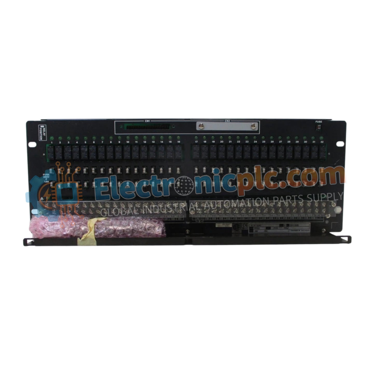
SARM55W-000 Mechanical Relay Board Yokogawa

SARM55W-000 Mechanical Relay Board Yokogawa

The Yokogawa SARM55W-000, also cataloged as the SARM55W-000 Relay Board, operates as a dedicated hardware component for 32-point contact output execution within process control systems.

Suffix Breakdown & Model Matrix

...
17 people are viewing this right now

AvailabilityIn stock

SKU: SARM55W-000
Vendor: Yokogawa
Related Series:

Shipping & Returns

Reliable Worldwide Delivery

  • Carriers: Shipped via DHL, FedEx, UPS, or USPS.
  • Dispatch: Orders processed in 1-2 business days and dispatched within 3-5 business days.
  • Tracking: Full tracking details provided via email upon shipment.

30-Day Money-Back Guarantee

  • Guarantee: 30-day return window for in-stock, factory-sealed products.
  • Condition: Items must be unopened, unused, and in original packaging.
  • Authenticity: We guarantee 100% original and authentic hardware.

Need more details? Read our fullShipping PolicyandRefund Policy.

Authenticity & Warranty

  • Genuine Guarantee: We supply only 100% original, brand-new, and factory-sealed industrial automation parts.
  • Full Coverage: Every component is backed by a 12-month comprehensive warranty from the date of purchase.
  • Traceability: All products come with original factory documentation and accessories for full industrial compliance.

Technical Support & Sourcing

  • Expert Assistance: Our technical team provides free consultation to help you verify compatibility for DCS and PLC systems.
  • Rare Part Sourcing: Specializing in obsolete and hard-to-find components from Allen-Bradley, Siemens, ABB, HIMA, and more.
  • Bulk Inquiries: Contact us at pambo@5gplc.com for volume pricing or customized project quotes.
View full product details

The Yokogawa SARM55W-000, also cataloged as the SARM55W-000 Relay Board, operates as a dedicated hardware component for 32-point contact output execution within process control systems.

Suffix Breakdown & Model Matrix

  • SARM55W-000: Base designation for a 32-point mechanical relay board, configured for wet contact output operations with support for single or dual-redundant deployment.

Hardware Specifications

Parameter Specification
Model SARM55W-000
Brand Yokogawa
Origin JAPAN
Weight 2.2 kg
Dimensions 482.6 mm x 132.5 mm (3U)
Operating Temp 0 deg C to 50 deg C
Power Consumption 24 VDC, Max 0.65 A
Contact Points 32-point
Field Terminals M4 screws
Insulation Resistance 10 MOhm (500 VDC)
Max AC Load 250 VAC, 0.6 A per point
Max DC Load 30 VDC, 0.6 A; 125 VDC, 0.1 A

Process Control and Signal Isolation

The SARM55W-000 incorporates high-density relay switching, supporting both single and dual-redundant configurations for critical output paths. The board architecture features channel-to-channel isolation to prevent propagation of electrical faults from field devices back to the controller backplane. Galvanic isolation is enforced between the field device terminals and the internal logic circuitry, with a withstand voltage of 2 kV. This isolation profile, combined with the 500 VDC insulation testing capability, ensures deterministic signal path behavior in complex DCS environments.

Frequently Asked Questions

Q: Does the SARM55W-000 support hot-swapping while the system is energized?

A: No. Due to the nature of the mechanical relay contacts and the 24 VDC power distribution, the board must be isolated from the power supply and control bus before any installation or maintenance procedures are performed.

Q: What is the minimum load requirement for the mechanical relay contacts?

A: The contacts require a minimum load of 5 V at 10 mA to ensure stable contact closure and prevent premature oxidation of the mechanical relay surfaces.

Field Installation Guidelines

  1. Ensure the board is mounted in a 3U-compliant rack enclosure, maintaining clearance for proper heat dissipation within the 0 deg C to 50 deg C ambient range.
  2. Terminate all field signal wires to the M4 screw terminals, ensuring a secure mechanical connection to prevent high-resistance contact points.
  3. Verify that the field device power supply is fused appropriately to protect the dual-line input, as the system supports a maximum current of 9.6 A for AC or 30 VDC loads.
  4. Maintain separation between high-voltage switching circuits and low-voltage logic signal wiring within the cabinet to prevent inductive noise injection.
  5. Check that the insulation resistance exceeds 10 MOhm using a 500 VDC source before initial commissioning to confirm integrity against casing grounds.