My Cart
0 items
Genuine Automation Parts | Worldwide Express Delivery | 12-Month Warranty — [GET A QUOTE]

The Yokogawa SB401-11 S1 (SB401-11 S1 ESB Bus Interface Slave Module) is a high-performance communication interface designed for integration within distributed control systems. This module serves as a critical link...
Availability: Low stock: 99 left
Reliable Worldwide Delivery
30-Day Money-Back Guarantee
Need more details? Read our fullShipping PolicyandRefund Policy.
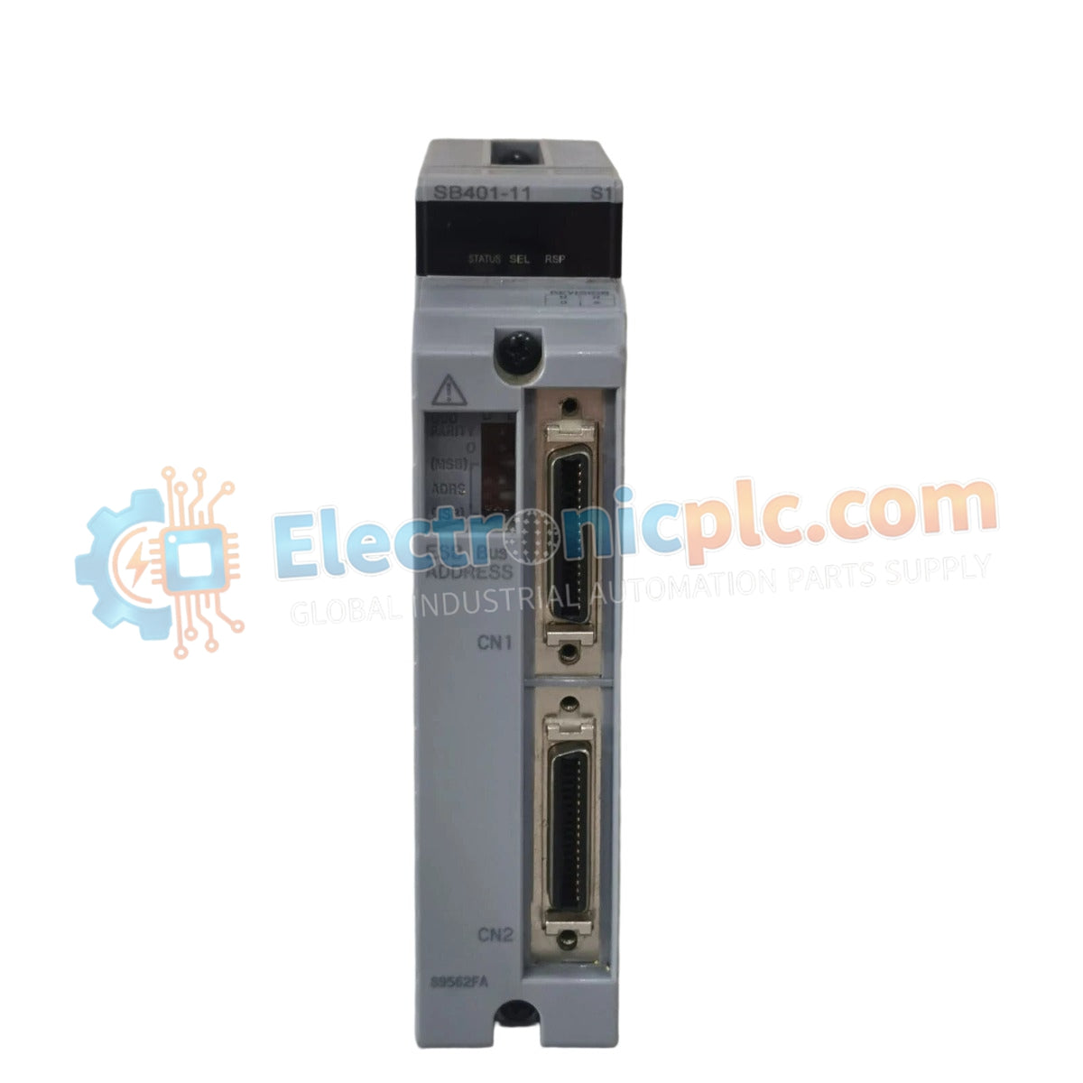

The Yokogawa SB401-11 S1 (SB401-11 S1 ESB Bus Interface Slave Module) is a high-performance communication interface designed for integration within distributed control systems. This module serves as a critical link between the Field Control Unit (FCU) and remote I/O subsystems, facilitating data synchronization and command routing across the Extended Standard Bus (ESB) architecture in upgraded Yokogawa CENTUM platforms.
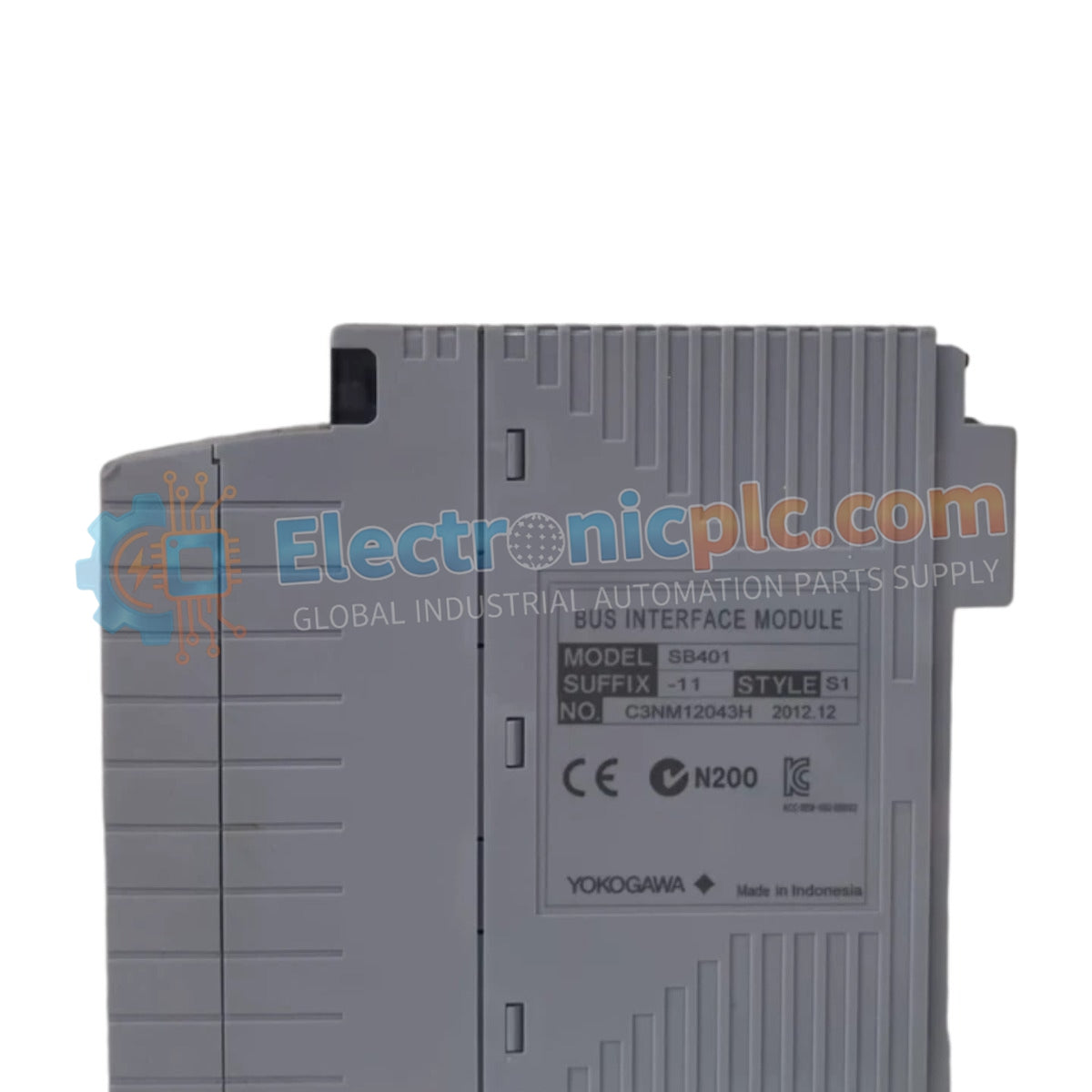
The SB401-11 S1 designation specifies an advanced hardware revision of the SB401-11 series. The "S1" suffix signifies a refinement in the backplane communication logic, providing improved signal stability and enhanced compatibility with modern control station firmware that requires higher bus throughput for dual-redundant network configurations.
| Parameter | Specification |
|---|---|
| Model | SB401-11 S1 |
| Brand | Yokogawa |
| Origin | Japan |
| Weight | 0.5 kg |
| Dimensions | 2.5 cm x 12.7 cm x 12.7 cm |
| Operating Temp | 0 to 60 deg C |
| Power Consumption | 4 W (typical) |
| Interface Type | ESB Bus Slave (Single-Port) |
The SB401-11 S1 integrates into the DCS architecture to provide deterministic communication between the control processor and remote I/O nodes. Engineered specifically for dual-redundant ESB bus environments, the module supports continuous data availability, ensuring that if a primary communication link encounters a fault, the system maintains stable data exchange. Its design incorporates channel-to-channel isolation to decouple the ESB bus from field-side electrical noise, preventing ground potential differences from impacting the integrity of the data stream.
Q: Is the SB401-11 S1 backward compatible with the standard SB401-11 module?
A: In most CENTUM VP configurations, the S1 revision acts as a functional upgrade; however, verify that your control system engineering station software and controller firmware explicitly support the S1 revision for the target slot.
Q: Does this module require specific bus termination settings?
A: Yes, proper bus termination is mandatory at the physical ends of the ESB bus segment to prevent signal reflections and ensure long-term network stability in redundant environments.


