My Cart
0 items
Genuine Automation Parts | Worldwide Express Delivery | 12-Month Warranty — [GET A QUOTE]

The Yokogawa SB401-50 (SB401-50 ESB Bus Interface Slave Module) is a core communication component designed to manage data exchange between field control stations and remote I/O slave nodes within distributed...
Availability: Low stock: 99 left
Reliable Worldwide Delivery
30-Day Money-Back Guarantee
Need more details? Read our fullShipping PolicyandRefund Policy.


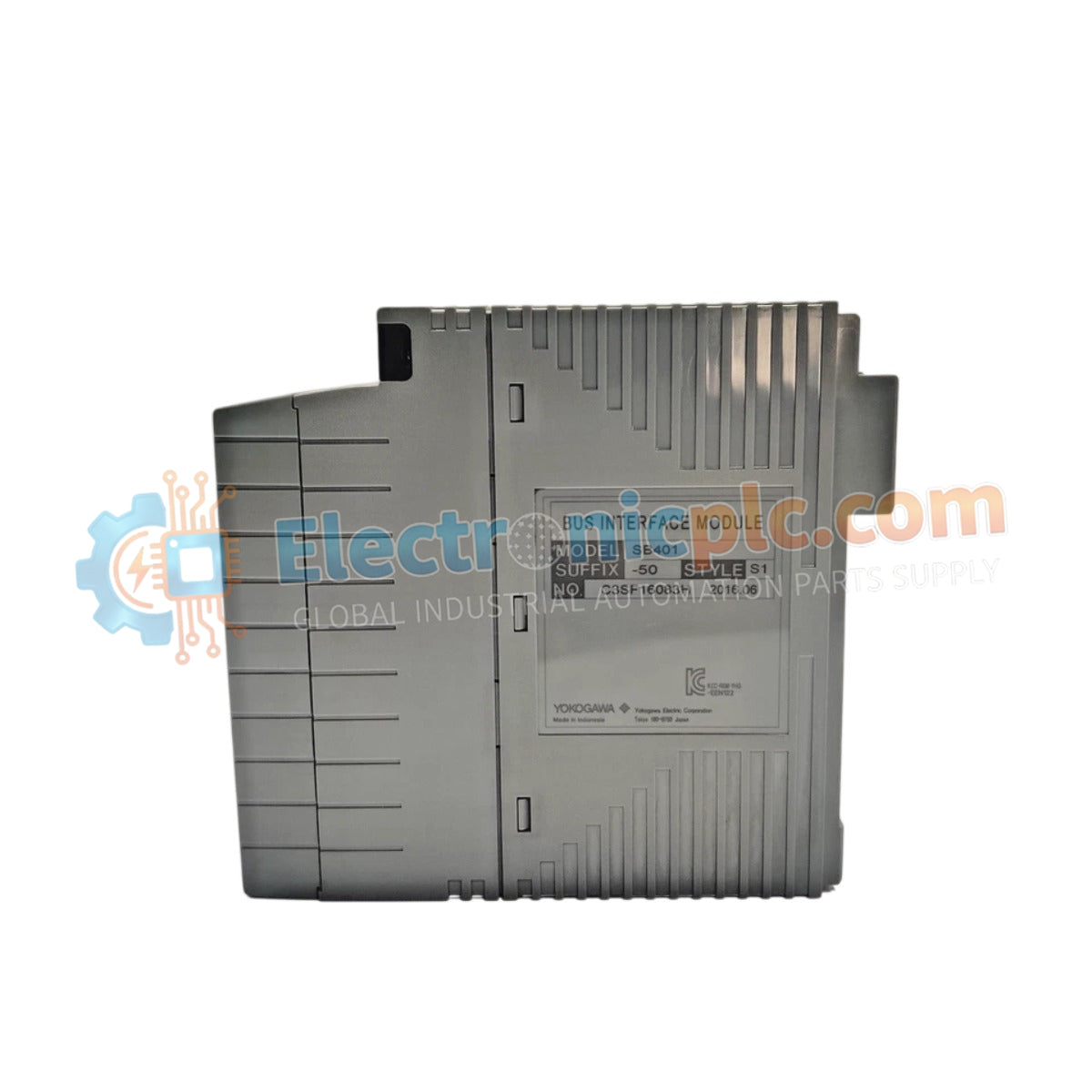
The Yokogawa SB401-50 (SB401-50 ESB Bus Interface Slave Module) is a core communication component designed to manage data exchange between field control stations and remote I/O slave nodes within distributed control systems (DCS). Despite being labeled in some records as a "Power Supply," the module serves fundamentally as an ESB (Extended Standard Bus) interface that enables deterministic communication across Yokogawa CENTUM platforms.
| Parameter | Specification |
|---|---|
| Model | SB401-50 |
| Brand | Yokogawa |
| Origin | Japan |
| Weight | 0.2 kg |
| Dimensions | 5.1 cm x 20.3 cm x 20.3 cm |
| Operating Temp | 0 to 60 deg C |
| Power Consumption | 7 W (nominal) |
| Interface Type | ESB Bus Slave |
The SB401-50 integrates into the DCS architecture to facilitate reliable, high-speed data synchronization between the central controller and remote field devices. By acting as a slave interface on the ESB bus, it ensures that process data, alarm signals, and control commands are transmitted with consistent, predictable latency. The module's internal circuitry provides essential electrical isolation to decouple the bus from field-induced electrical noise, protecting the integrity of the communication channel.
Q: Is this module truly a power supply or a communication interface?
A: While it may be categorized under power or modular accessories in some inventory systems due to its role in the rack power structure, its primary function is an ESB Bus Interface Slave. It handles the data routing and communication link between the master controller and the remote I/O nodes.
Q: Does the module require specific firmware to function?
A: Yes, the SB401-50 operates based on the system-wide firmware version of the CENTUM control station. Ensure your system engineering software is updated to match the hardware requirements of the installed module.


