
My Cart
0 items
Genuine Automation Parts | Worldwide Express Delivery | 12-Month Warranty — [GET A QUOTE]

Configured for diagnostic validation in digital input instrumentation loops, the YOKOGAWA SCB110-S0 (SCB110-S0 Wiring Check Adapter) provides direct physical monitoring and verification of digital signal circuits across PLC and DCS platforms.
...Availability: In stock
Reliable Worldwide Delivery
30-Day Money-Back Guarantee
Need more details? Read our fullShipping PolicyandRefund Policy.


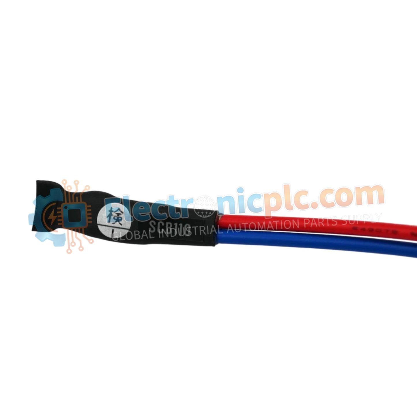
Configured for diagnostic validation in digital input instrumentation loops, the YOKOGAWA SCB110-S0 (SCB110-S0 Wiring Check Adapter) provides direct physical monitoring and verification of digital signal circuits across PLC and DCS platforms.
| Parameter | Specification |
|---|---|
| Model | SCB110-S0 |
| Brand | YOKOGAWA |
| Origin | Japan |
| Weight | 0.5kg |
| Dimensions | Standard terminal interface form factor |
| Operating Temp | Not specified |
| Power Consumption | Passive (Loop powered) |
| Input Type | Digital Input (DI) verification |
| Mounting | Terminal block interface |
| Protection | Standard industrial enclosure |
The SCB110-S0 is engineered to facilitate rapid verification of field wiring without requiring live signals from field transmitters. By acting as a diagnostic bridge, the adapter allows technicians to simulate input states, ensuring that channel-to-channel isolation and signal path integrity are confirmed prior to full system commissioning. This physical verification capability is essential for identifying wiring faults, such as open circuits or short-to-ground conditions, within complex digital I/O architectures.
Q: Does the SCB110-S0 require external power for wiring verification?
A: No, the adapter is a passive device designed to interface with the existing I/O module power supply. It utilizes the loop current to facilitate state verification during the testing phase.
Q: Can this adapter be left in the circuit during normal operation?
A: The SCB110-S0 is intended for diagnostic and commissioning purposes. It should be removed from the signal path once wiring verification is complete to ensure the I/O module operates within its design parameters.


