My Cart
0 items
Genuine Automation Parts | Worldwide Express Delivery | 12-Month Warranty — [GET A QUOTE]

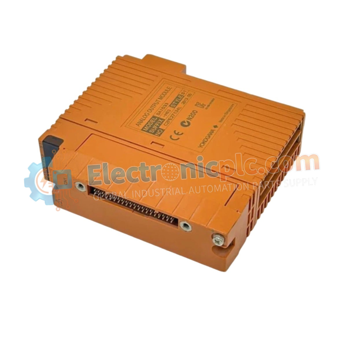
Configured for high-speed network bridging in distributed control systems, the Yokogawa SCE401-11 (SCE401-11) provides direct physical/electrical execution of S1 bus coupling between field control units and remote I/O nodes.
Availability: Low stock: 99 left
Reliable Worldwide Delivery
30-Day Money-Back Guarantee
Need more details? Read our fullShipping PolicyandRefund Policy.


Configured for high-speed network bridging in distributed control systems, the Yokogawa SCE401-11 (SCE401-11) provides direct physical/electrical execution of S1 bus coupling between field control units and remote I/O nodes.
| Parameter | Specification |
|---|---|
| Model | SCE401-11 |
| Brand | Yokogawa |
| Origin | Japan |
| Weight | Standard DCS module form factor |
| Dimensions | Industrial cabinet mount dimensions |
| Operating Temp | Industrial grade (consult system manual) |
| Interface | S1 Bus |
| Power Consumption | Refer to backplane power budget |
The SCE401-11 module serves as the critical communication interface for the S1 bus, enabling seamless data exchange across the control architecture. By acting as a bus coupler, it facilitates the expansion of the control system's I/O capacity while maintaining the deterministic timing required for real-time process monitoring. The module's internal circuitry manages signal conditioning and protocol arbitration, ensuring that high-speed communication packets remain synchronized between the central processor and the distributed field nodes.
Q: Can this module be used to bridge disparate network protocols?
A: The SCE401-11 is specifically designed for S1 bus coupling within the Yokogawa ecosystem. Bridging to non-native network protocols typically requires specialized gateway modules or communication interface cards.
Q: How do I verify the communication health of the S1 bus coupler?
A: System diagnostic tools provided with the control platform should be used to monitor link status, packet error rates, and heartbeat signals to ensure the coupler is participating correctly in the bus communication cycle.


