My Cart
0 items
Genuine Automation Parts | Worldwide Express Delivery | 12-Month Warranty — [GET A QUOTE]

Configured for high-speed, deterministic data transmission within the CENTUM VP control architecture, the YOKOGAWA SEC401-51 (SEC401 ESB Bus Coupler) acts as the critical bridge for signal synchronization between Field Control...
Availability: Low stock: 99 left
Reliable Worldwide Delivery
30-Day Money-Back Guarantee
Need more details? Read our fullShipping PolicyandRefund Policy.


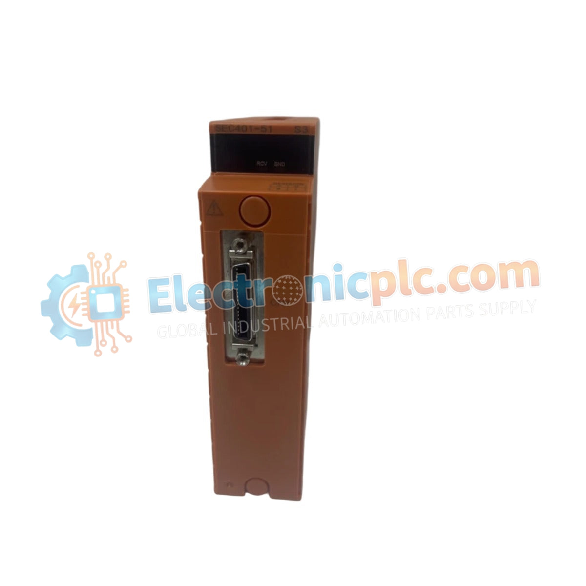
Configured for high-speed, deterministic data transmission within the CENTUM VP control architecture, the YOKOGAWA SEC401-51 (SEC401 ESB Bus Coupler) acts as the critical bridge for signal synchronization between Field Control Units (FCUs) and remote I/O node units.
| Parameter | Specification |
|---|---|
| Model | SEC401-51 |
| Brand | YOKOGAWA |
| Origin | Japan |
| Weight | 0.3 kg |
| Dimensions | 2.2 x 12.4 x 12.6 cm |
| Operating Temp | Standard industrial range |
| Power Consumption | Subject to backplane supply |
| Bus Interface | ESB Bus |
| Mounting Type | Rack mount |
The SEC401-51 module serves as the primary interface managing the synchronization of data packets across the ESB bus. Its internal architecture is designed to handle high-density I/O traffic with minimal latency, ensuring that process control commands and feedback loops remain stable. The module features integrated galvanic isolation, which protects the sensitive system bus from transient electrical interference originating in field-side wiring. By maintaining precise impedance matching across the bus segment, the SEC401-51 prevents signal reflection and jitter, ensuring that the control system can reliably execute time-critical operations without packet loss.
Q: Is the SEC401-51 module hot-swappable during system operation?
A: No. This module is not designed for hot-swapping. The control station power must be fully de-energized and appropriate safety protocols must be followed before installing or removing the module to prevent electrical damage to the backplane or the coupler itself.
Q: How does the SEC401-51 differ from other ESB bus coupler variants?
A: The suffix "-51" indicates specific hardware revisions and interface parameters tailored for compatibility with defined CENTUM VP control station configurations. Always verify that the model and suffix code match your existing system documentation before proceeding with a replacement.


