
My Cart
0 items
Genuine Automation Parts | Worldwide Express Delivery | 12-Month Warranty — [GET A QUOTE]

Configured for high-density signal transmission in YOKOGAWA control networks, the YOKOGAWA AKB335-M010 (AKB335 Signal Cable) provides direct physical data link execution between field interface modules and system controllers.
Availability: In stock
Reliable Worldwide Delivery
30-Day Money-Back Guarantee
Need more details? Read our fullShipping PolicyandRefund Policy.


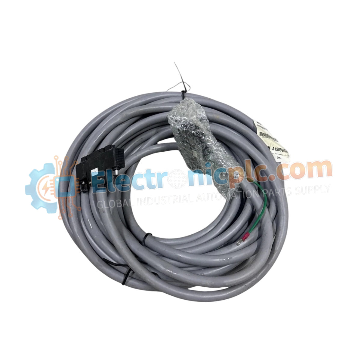
Configured for high-density signal transmission in YOKOGAWA control networks, the YOKOGAWA AKB335-M010 (AKB335 Signal Cable) provides direct physical data link execution between field interface modules and system controllers.
| Parameter | Specification |
|---|---|
| Model | AKB335-M010 |
| Brand | YOKOGAWA |
| Origin | Japan |
| Weight | 0.5 kg |
| Dimensions | 10 meters length |
| Operating Temp | -10 deg C to 60 deg C |
| Power Consumption | N/A (Passive interconnect) |
| Connector Pin Count | 50 pins |
| Impedance | 100 Ohms |
| Max Voltage | 300 V |
The AKB335-M010 utilizes a dual-layer foil and braid shield construction to maintain signal fidelity in environments prone to electromagnetic interference. Designed to support 4-20 mA HART loop protocol architectures, the oxygen-free copper conductors ensure minimal resistance over the 10 meter span. This configuration facilitates consistent channel-to-channel signal propagation, ensuring that analog data remains within required accuracy tolerances when interfaced with remote I/O subsystems.
Q: Can this cable be shortened in the field for custom installation requirements?
A: Field modification is not recommended as it compromises the impedance characteristics and the integrity of the 50-pin connector termination. Any alteration may induce signal reflections or crosstalk within the high-density connection.
Q: Is this cable compatible with high-frequency communication modules?
A: The AKB335-M010 supports operating frequencies up to 1 GHz. Ensure that the specific module interface impedance matches the 100 Ohm specification of the cable to avoid signal degradation during high-speed data transmission.


