My Cart
0 items
Genuine Automation Parts | Worldwide Express Delivery | 12-Month Warranty — [GET A QUOTE]

Configured for high-density I/O connectivity within control system cabinets, the Yokogawa AKB336-M002 (AKB336-M002 Signal Cable) provides direct physical signal transmission between I/O modules and terminal boards.
Availability: In stock
Reliable Worldwide Delivery
30-Day Money-Back Guarantee
Need more details? Read our fullShipping PolicyandRefund Policy.
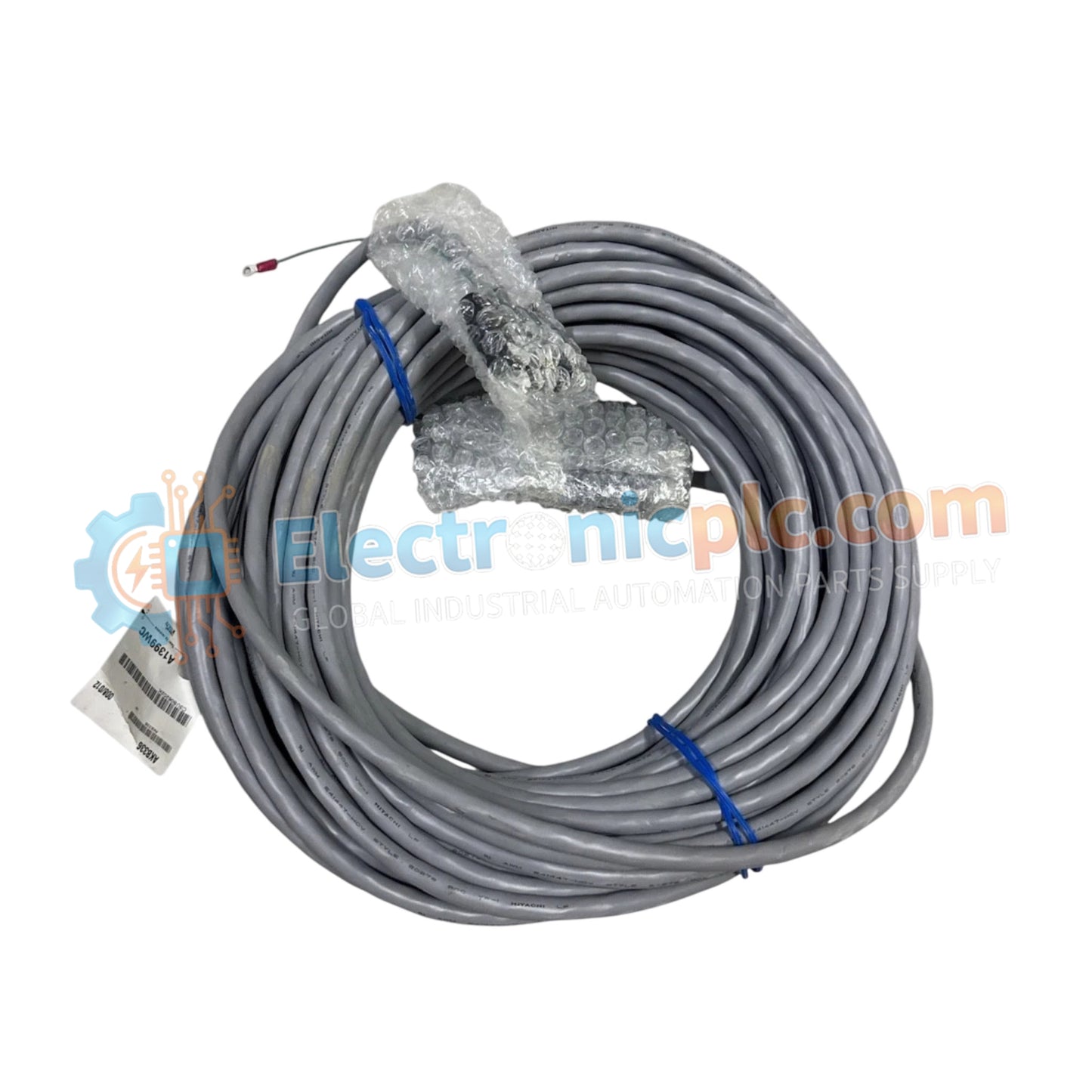

Configured for high-density I/O connectivity within control system cabinets, the Yokogawa AKB336-M002 (AKB336-M002 Signal Cable) provides direct physical signal transmission between I/O modules and terminal boards.
| Model | Component Description |
|---|---|
| AKB336 | Base I/O Signal Cable series |
| -M002 | Cable length configuration (2 meters) |
| Parameter | Specification |
|---|---|
| Model | AKB336-M002 |
| Brand | Yokogawa |
| Origin | japan |
| Weight | 0.65kg |
| Dimensions | 2 meters length |
| Operating Temp | -20 deg C to +70 deg C |
| Power Consumption | Passive component |
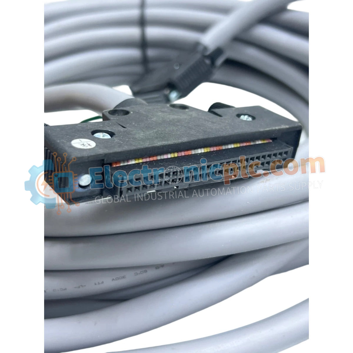
| Connector Config | 20-pin to 20-pin |
| Connector Type | Solderless lug with M4 screws |
| Length Tolerance | +5%, -0% |
The AKB336-M002 is engineered to maintain low-latency data flow within Yokogawa CENTUM VP and ProSafe-RS architectures. The cable utilizes intrinsic safety (Ex i) barrier-compatible construction where required and provides DIN-rail mounting stability when used in conjunction with secondary conduit routing. The assembly offers surge voltage protection limits necessary for maintaining communication link stability in high-EMI industrial zones. By adhering to standardized pin-out configurations, the cable ensures protocol conversion latencies are kept within the precise millisecond tolerances required for deterministic I/O communication.
Q: Can the 20-pin connector be re-terminated in the field?
A: No. The connectors are factory-molded and terminated to ensure consistent impedance and shielding integrity. Field modification will compromise the mechanical and electrical specifications of the cable assembly.
Q: What is the recommended tightening torque for the M4 connector screws?
A: Tighten the M4 screws to a value consistent with industrial standard practices for terminal blocks, typically 0.8 to 1.2 Nm, ensuring a secure electrical contact without damaging the lug or the terminal board threads.


