
My Cart
0 items
Genuine Automation Parts | Worldwide Express Delivery | 12-Month Warranty — [GET A QUOTE]

Configured for signal conditioning in industrial networks, the Yokogawa KFD2-STC4-1 (KFD2-STC4-1 SMART Transmitter Power Supply) provides direct physical/electrical execution of signal isolation and transmitter power distribution.
Availability: In stock
Reliable Worldwide Delivery
30-Day Money-Back Guarantee
Need more details? Read our fullShipping PolicyandRefund Policy.


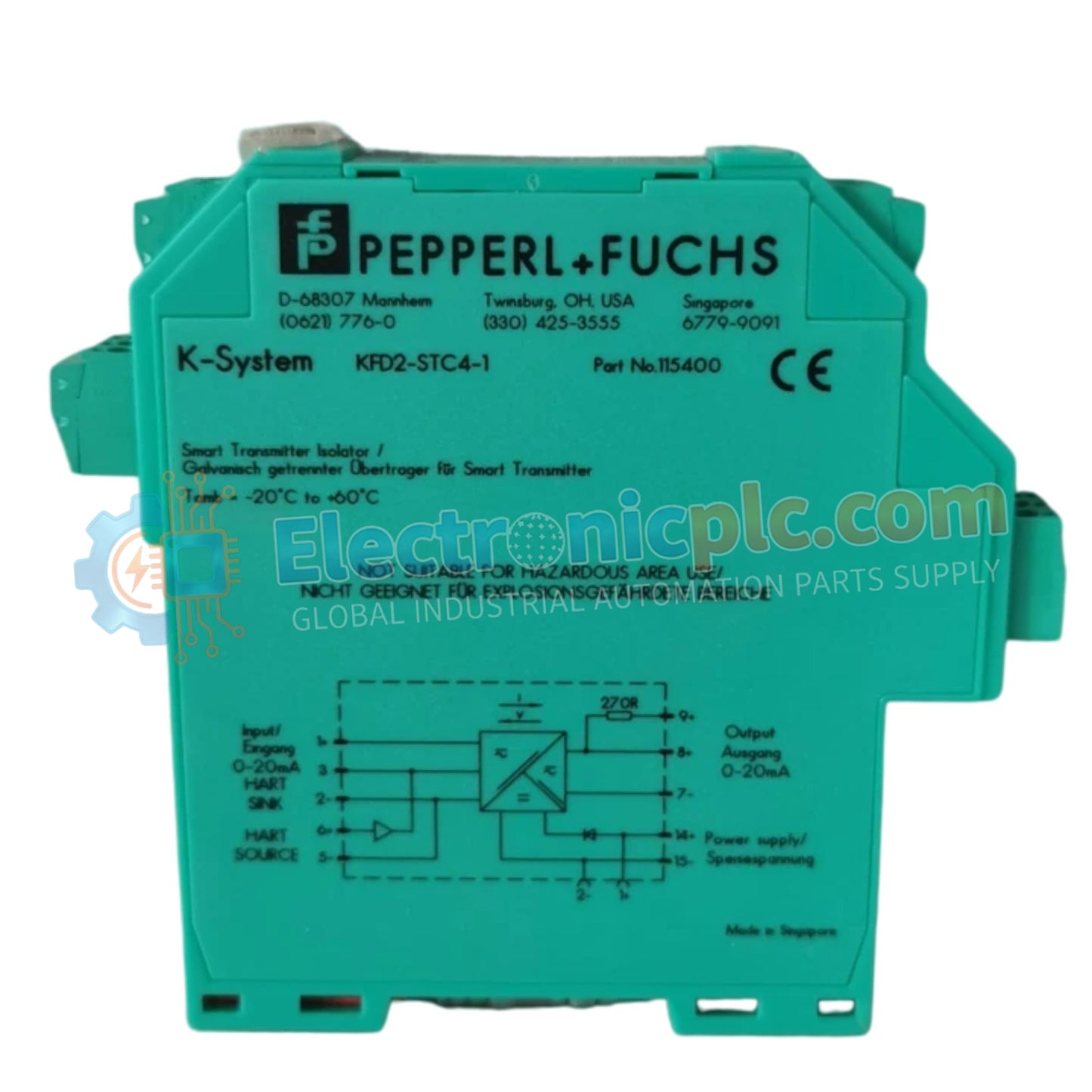
Configured for signal conditioning in industrial networks, the Yokogawa KFD2-STC4-1 (KFD2-STC4-1 SMART Transmitter Power Supply) provides direct physical/electrical execution of signal isolation and transmitter power distribution.
| Parameter | Specification |
|---|---|
| Model | KFD2-STC4-1 |
| Brand | Yokogawa |
| Origin | Germany |
| Weight | 0.15 kg |
| Dimensions | 20 mm x 119 mm x 115 mm |
| Operating Temp | -20 deg C to 60 deg C |
| Power Consumption | 24 VDC (via Power Rail) |
| Input | 2-wire / 3-wire SMART transmitters |
| Output | 0/4-20 mA current |
| Safety Rating | SIL2 acc. to IEC 61508 |
The KFD2-STC4-1 incorporates intrinsic safety (Ex i) barriers to ensure safe operation in hazardous area loops. These barriers limit the electrical energy transmitted to the field instrumentation, preventing ignition sources in volatile atmospheres. The module provides galvanic isolation between the input and output circuits, eliminating ground loops that often degrade signal accuracy in long-run industrial cabling. Furthermore, the unit facilitates protocol transparency for SMART transmitters, allowing bidirectional digital communication to pass through the 4-20 mA loop without attenuation or loss of HART data packets.
Q: Does the KFD2-STC4-1 support DIN-rail mounting stability?
A: Yes. The housing is designed for snap-on mounting onto a 35 mm DIN mounting rail. For high-vibration applications, ensure the unit is fully seated and locked into the rail profile to maintain electrical connectivity via the Power Rail system.
Q: Is the output signal capable of driving external loads while maintaining HART transparency?
A: Yes. The output is a standard 0/4-20 mA active or passive current source. It is designed to accommodate the typical load impedance requirements of DCS or PLC analog input cards while preserving the integrity of the superimposed HART communication frequency.


