Skip to product information
1 of 3

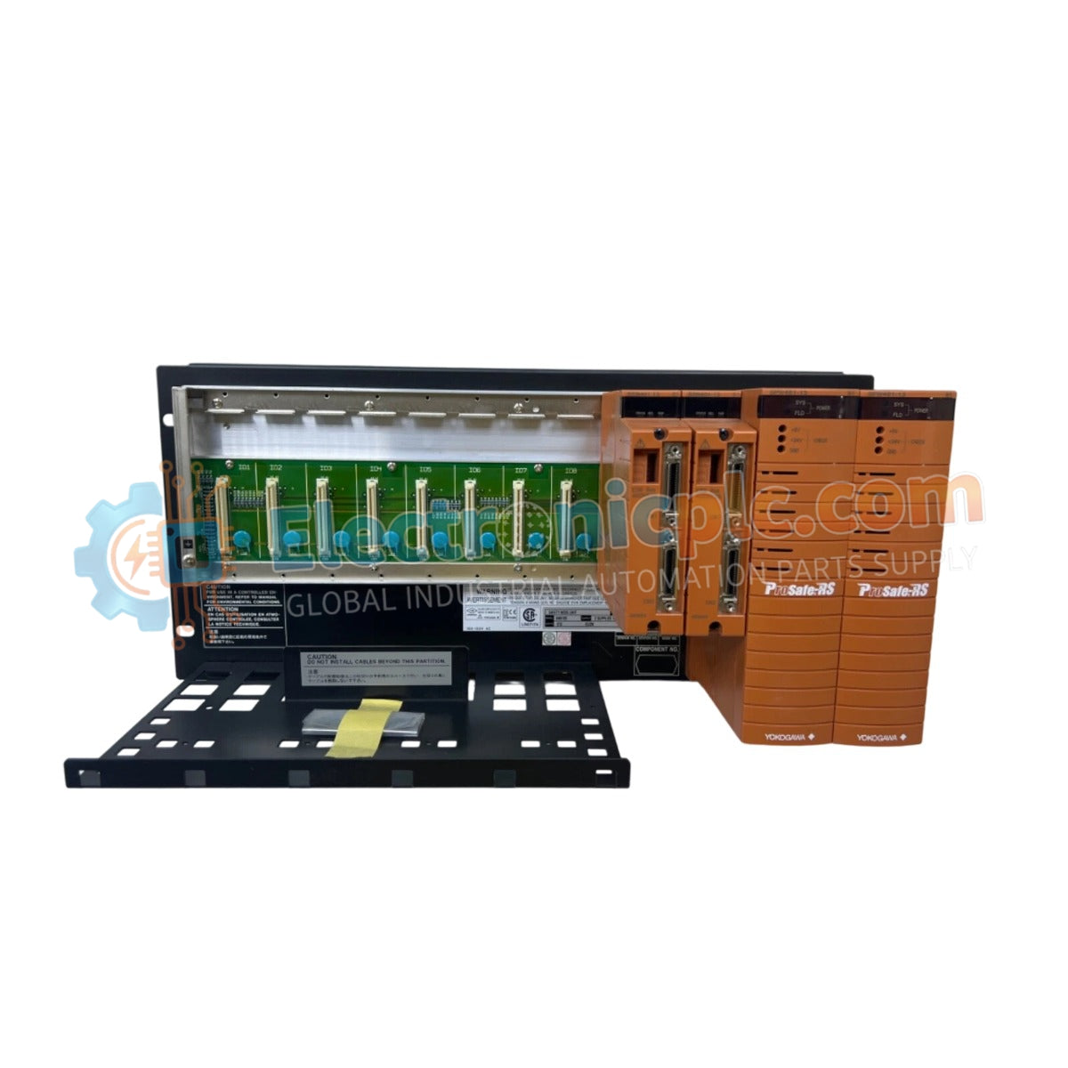
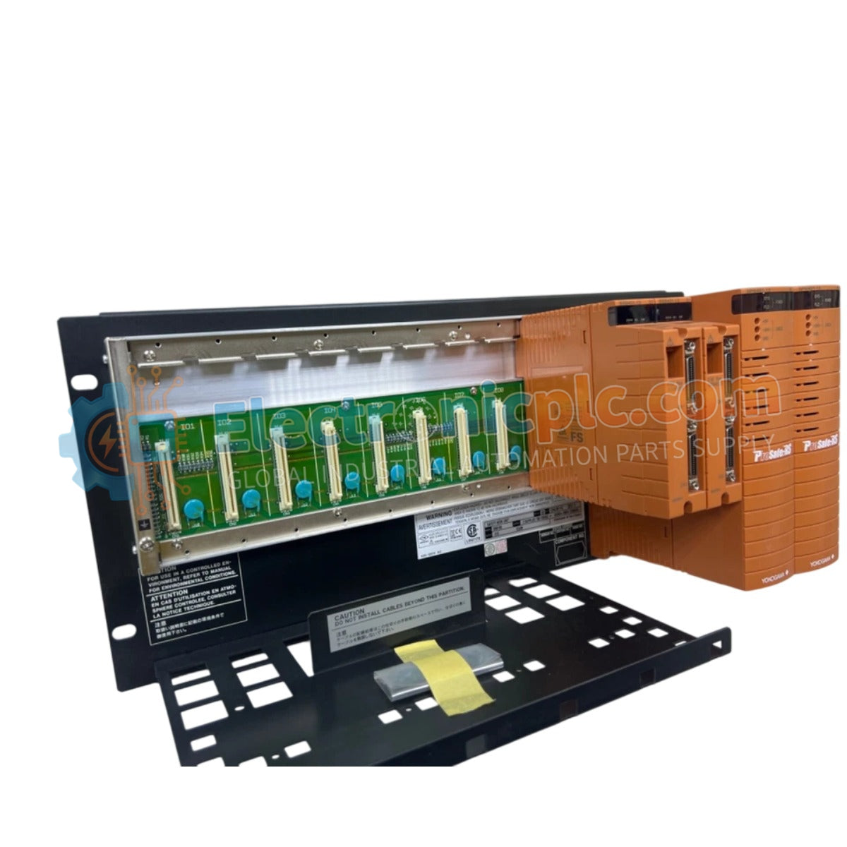
SNB10D-213/CN2N Safety Node Unit YOKOGAWA

SNB10D-213/CN2N Safety Node Unit YOKOGAWA

Configured for secure data transmission in ProSafe-RS safety control systems, the YOKOGAWA SNB10D-213/CN2N (SNB10D-213/CN2N Safety Node Unit) provides direct physical execution of ESB bus communication and power distribution. The unit...

24 people are viewing this right now

AvailabilityIn stock

SKU: SNB10D-213/CN2N
Vendor: Yokogawa
Category: Safety Node Unit
Related Series:

Shipping & Returns

Reliable Worldwide Delivery

  • Carriers: Shipped via DHL, FedEx, UPS, or USPS.
  • Dispatch: Orders processed in 1-2 business days and dispatched within 3-5 business days.
  • Tracking: Full tracking details provided via email upon shipment.

30-Day Money-Back Guarantee

  • Guarantee: 30-day return window for in-stock, factory-sealed products.
  • Condition: Items must be unopened, unused, and in original packaging.
  • Authenticity: We guarantee 100% original and authentic hardware.

Need more details? Read our fullShipping PolicyandRefund Policy.
Authenticity & Warranty

  • Genuine Guarantee: We supply only 100% original, brand-new, and factory-sealed industrial automation parts.
  • Full Coverage: Every component is backed by a 12-month comprehensive warranty from the date of purchase.
  • Traceability: All products come with original factory documentation and accessories for full industrial compliance.

Technical Support & Sourcing

  • Expert Assistance: Our technical team provides free consultation to help you verify compatibility for DCS and PLC systems.
  • Rare Part Sourcing: Specializing in obsolete and hard-to-find components from Allen-Bradley, Siemens, ABB, HIMA, and more.
  • Bulk Inquiries: Contact us at pambo@5gplc.com for volume pricing or customized project quotes.
View full product details

Configured for secure data transmission in ProSafe-RS safety control systems, the YOKOGAWA SNB10D-213/CN2N (SNB10D-213/CN2N Safety Node Unit) provides direct physical execution of ESB bus communication and power distribution. The unit acts as a foundational hardware interface for critical safety logic execution across industrial automation platforms.

Suffix Breakdown & Model Matrix

  • SNB10D: Base model designation for the rack-mountable Safety Node Unit.
  • 2: Input power configuration designation.
  • 13: Hardware revision and interface specification.
  • CN2N: Suffix code indicating specific regional or configuration standard adherence.

Hardware Specifications

Parameter Specification
Model SNB10D-213/CN2N
Brand YOKOGAWA
Origin Japan
Weight 4.9 kg
Dimensions 5.1 cm x 20.3 cm x 14.6 cm
Operating Temp -20 to 70 deg C
Power Consumption 120 W (AC) / 5.5 A (24 VDC)
Communication ESB Bus
Mounting 19-inch rack mount

Galvanic Isolation and Safety Integrity

The SNB10D-213/CN2N incorporates galvanic isolation to ensure the electrical separation of the ESB bus from field instrumentation, preventing the propagation of transient surges within the safety instrumented system. This unit is designed for fail-safe state execution, ensuring that in the event of internal power fluctuation or communication loss, the safety node maintains a predetermined secure state. The modular design supports redundant power input configurations, minimizing the risk of total system shutdown due to single-source power failure.

Frequently Asked Questions

Q: Can this safety node be installed in environments with high electromagnetic interference?

A: Yes, provided the unit is properly mounted in an earthed 19-inch rack and all cabling utilizes proper shielding techniques. The unit is designed to meet strict industrial safety standards for operation in demanding environments.

Q: How does the unit handle redundant power supply inputs?

A: The SNB10D-213/CN2N is engineered to manage dual power inputs independently; if one power source drops below operational thresholds, the internal logic switches to the remaining healthy supply without interrupting the ESB bus communication.

Field Installation Guidelines

  1. Mount the unit in a standard 19-inch rack. Ensure that the rack is connected to a high-integrity functional earth to provide a low-impedance path for noise suppression.
  2. Verify that the input power voltage matches the specific jumper or terminal configuration (100–120 VAC, 220–240 VAC, or 24 VDC). Incorrect voltage application can lead to permanent component failure.
  3. Utilize dedicated ESB bus cabling. Ensure connectors are fully seated and that the cable is secured to prevent mechanical stress on the interface port.
  4. Maintain a minimum clearance of 5 cm around the heat dissipation vents to allow for adequate airflow within the -20 to 70 deg C operating range.
  5. Perform a system-level loop verification after installation to confirm that the safety node is correctly recognized by the ProSafe-RS controller node.