My Cart
0 items
Genuine Automation Parts | Worldwide Express Delivery | 12-Month Warranty — [GET A QUOTE]

Configured for distributed I/O management in safety-instrumented systems, the YOKOGAWA SNB10D-215/CU2N (SNB10D Safety Node Unit) provides direct physical and electrical execution of ESB bus signal routing and I/O module communication...
Availability: Low stock: 99 left
Reliable Worldwide Delivery
30-Day Money-Back Guarantee
Need more details? Read our fullShipping PolicyandRefund Policy.


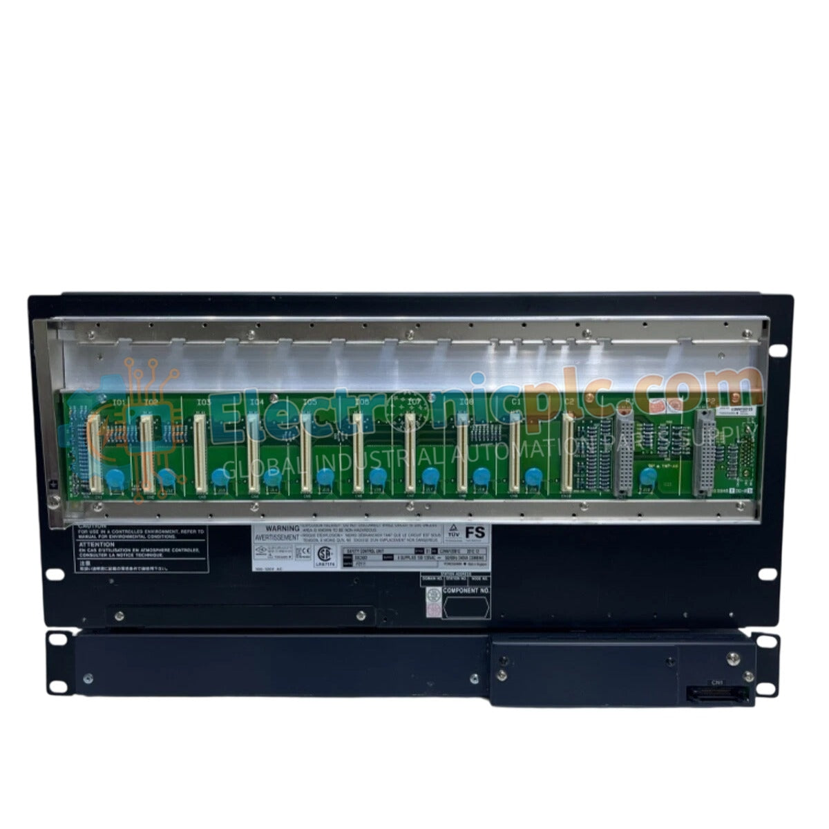
Configured for distributed I/O management in safety-instrumented systems, the YOKOGAWA SNB10D-215/CU2N (SNB10D Safety Node Unit) provides direct physical and electrical execution of ESB bus signal routing and I/O module communication within the CENTUM VP and ProSafe-RS control environments.
The SNB10D series utilizes a modular suffix code system to define hardware configuration and electrical standards:
| Parameter | Specification |
|---|---|
| Model | SNB10D-215/CU2N |
| Brand | YOKOGAWA |
| Origin | Japan |
| Weight | 5.52 kg |
| Dimensions | 18.4 x 15 x 3 cm |
| Operating Temp | Standard industrial range |
| Power Consumption | Subject to node load |
| Bus Interface | ESB Bus |
| Function | Safety Node communication |
The SNB10D-215/CU2N is engineered to maintain high-integrity communication within safety-instrumented systems. The internal architecture facilitates galvanic isolation between the ESB bus interface and the local I/O backplane, effectively mitigating ground loops and common-mode noise that could trigger spurious trips. This unit serves as the physical anchor for safety I/O modules, ensuring that fail-safe state execution signals are transmitted with deterministic latency to the field control unit. The unit is optimized for high-density I/O configurations while maintaining strict adherence to safety bus impedance specifications to prevent signal corruption.
Q: Does the SNB10D-215/CU2N support hot-swapping of safety I/O modules?
A: Yes, the node unit is designed to allow for the replacement of individual I/O modules during operation, provided the specific safety integrity level (SIL) documentation and local site protocols permit online maintenance.
Q: How does the /CU2N suffix affect integration with existing nodes?
A: The /CU2N suffix defines specific interface parameters and cooling/protection configurations. It is fully compatible with standard ESB bus backplanes, but verification of the local node rack configuration is required before installation.


