My Cart
0 items
Genuine Automation Parts | Worldwide Express Delivery | 12-Month Warranty — [GET A QUOTE]

Configured for extended-distance signal transmission within Yokogawa control networks, the YOKOGAWA SNT401-53 S1 (SNT401-53 S1 Optical ESB Bus Repeater Module) provides optical signal conversion for the Extended Synchronous Bus (ESB)....
Availability: Low stock: 99 left
Reliable Worldwide Delivery
30-Day Money-Back Guarantee
Need more details? Read our fullShipping PolicyandRefund Policy.

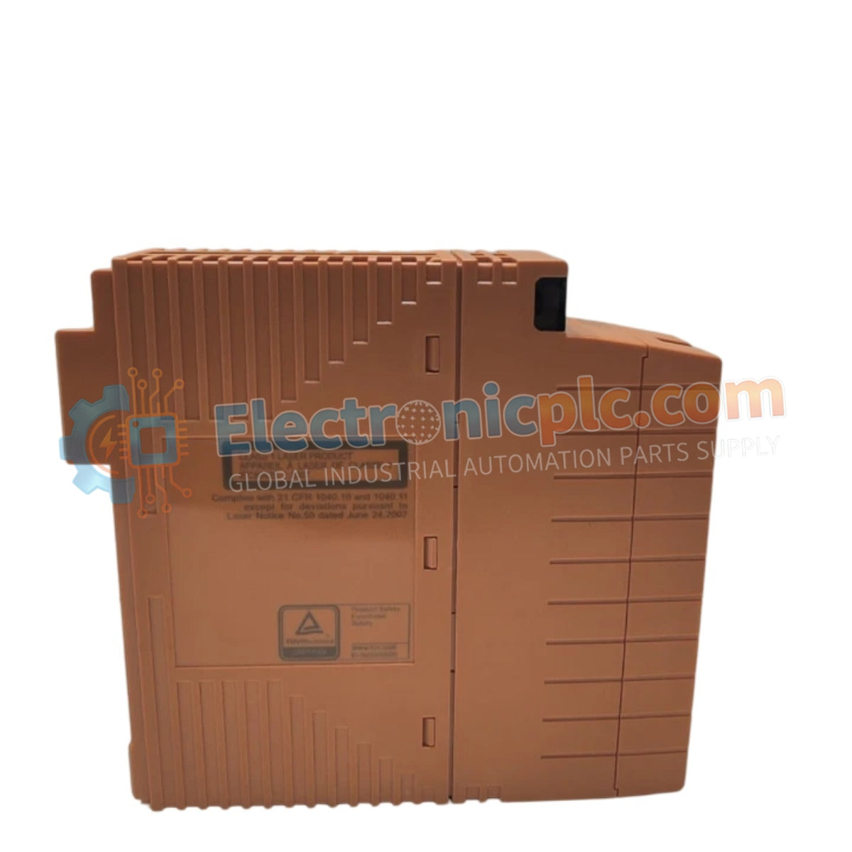
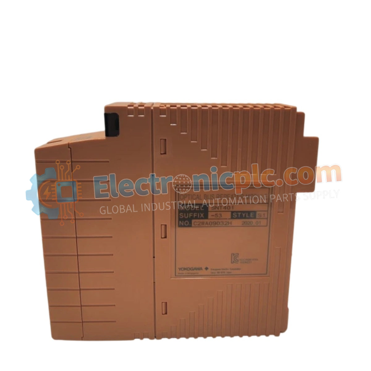
Configured for extended-distance signal transmission within Yokogawa control networks, the YOKOGAWA SNT401-53 S1 (SNT401-53 S1 Optical ESB Bus Repeater Module) provides optical signal conversion for the Extended Synchronous Bus (ESB). This hardware component allows for the bridging of I/O nodes over longer physical distances than standard copper cabling permits, utilizing fiber-optic media to maintain high-speed, deterministic data exchange across distributed process areas.
| Parameter | Specification |
|---|---|
| Model | SNT401-53 S1 |
| Brand | Yokogawa |
| Origin | Japan |
| Weight | 0.3 kg |
| Dimensions | 2.2 cm x 12.4 cm x 12.6 cm |
| Operating Temp | Standard industrial ambient range |
| Power Consumption | Nominal DCS backplane power supply |
| Function | Optical signal conversion for ESB bus |
The SNT401-53 S1 converts electrical ESB signals into optical pulses, enabling reliable data transmission between the Field Control Unit (FCU) and remote I/O nodes. Optical transmission provides inherent immunity to electromagnetic interference (EMI) and radio frequency interference (RFI), making it the ideal solution for environments with high electrical noise, such as those near high-voltage switchgear or heavy motor drives.
Q: Can this module be used to daisy-chain I/O nodes over long distances?
A: The SNT401 is designed to extend the reach of the ESB bus using fiber optics. When designing the topology, ensure the total fiber length and the number of repeaters do not exceed the timing and signal attenuation limits specified by the Yokogawa system planning manual.
Q: What type of fiber-optic connector is required?
A: Ensure the interface matches the specific SNT401-53 hardware specification. Standard industrial fiber interfaces are typically used; verify the fiber core diameter (e.g., multimode vs. single-mode) compatibility before cable procurement.


