My Cart
0 items
Genuine Automation Parts | Worldwide Express Delivery | 12-Month Warranty — [GET A QUOTE]

The YOKOGAWA SPW481-13 S1, also cataloged as the SPW481 Power Supply Module, operates as a dedicated hardware component for power regulation and distribution within Yokogawa DCS platforms. This module executes...
Availability: Low stock: 99 left
Reliable Worldwide Delivery
30-Day Money-Back Guarantee
Need more details? Read our fullShipping PolicyandRefund Policy.


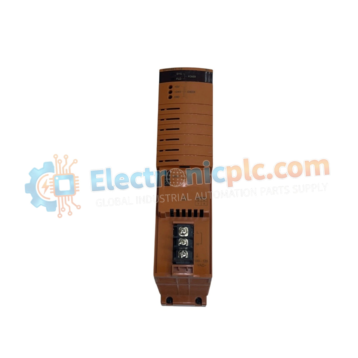
The YOKOGAWA SPW481-13 S1, also cataloged as the SPW481 Power Supply Module, operates as a dedicated hardware component for power regulation and distribution within Yokogawa DCS platforms. This module executes the conversion of incoming supply voltage into regulated DC output, maintaining the operational stability required for backplane-mounted control cards and integrated field instrumentation.
The model identifier SPW481-13 S1 designates a specific hardware iteration. The "S1" suffix indicates a revised board layout and component selection optimized for current-generation Yokogawa DCS chassis, ensuring mechanical form factor compatibility and standard electrical interface matching.
| Parameter | Specification |
|---|---|
| Model | SPW481-13 S1 |
| Brand | Yokogawa |
| Origin | Japan |
| Weight | 0.9 kg |
| Dimensions | 5.1 cm x 20.3 cm x 14.6 cm |
| Operating Temp | 0 deg C to 50 deg C |
| Power Consumption | Load dependent |
The SPW481-13 S1 facilitates stable voltage rails necessary for process control continuity. The unit incorporates channel-to-channel isolation to prevent ground loops and electrical noise injection into the control bus. Consistent voltage delivery is maintained across varying load conditions to ensure the integrity of the 4-20 mA HART loop protocol utilized by downstream instrumentation. Cold junction compensation (CJC) and precise thermal management are implemented within the power stage to maintain performance accuracy across the operational temperature range.
Q: Is the SPW481-13 S1 compatible with redundant power configurations?
A: Yes, this module supports load-sharing configurations when installed in redundant pairs within a compatible Yokogawa chassis. Ensure both modules are active and connected to independent power sources to maintain zero-switchover time in the event of a single module failure.
Q: Does the module support hot-swapping?
A: The SPW481-13 S1 supports hot-swapping within properly configured backplanes. Ensure that the associated rack is equipped with protective circuitry to handle transient surges during the engagement of the backplane connector pins.


