My Cart
0 items
Genuine Automation Parts | Worldwide Express Delivery | 12-Month Warranty — [GET A QUOTE]

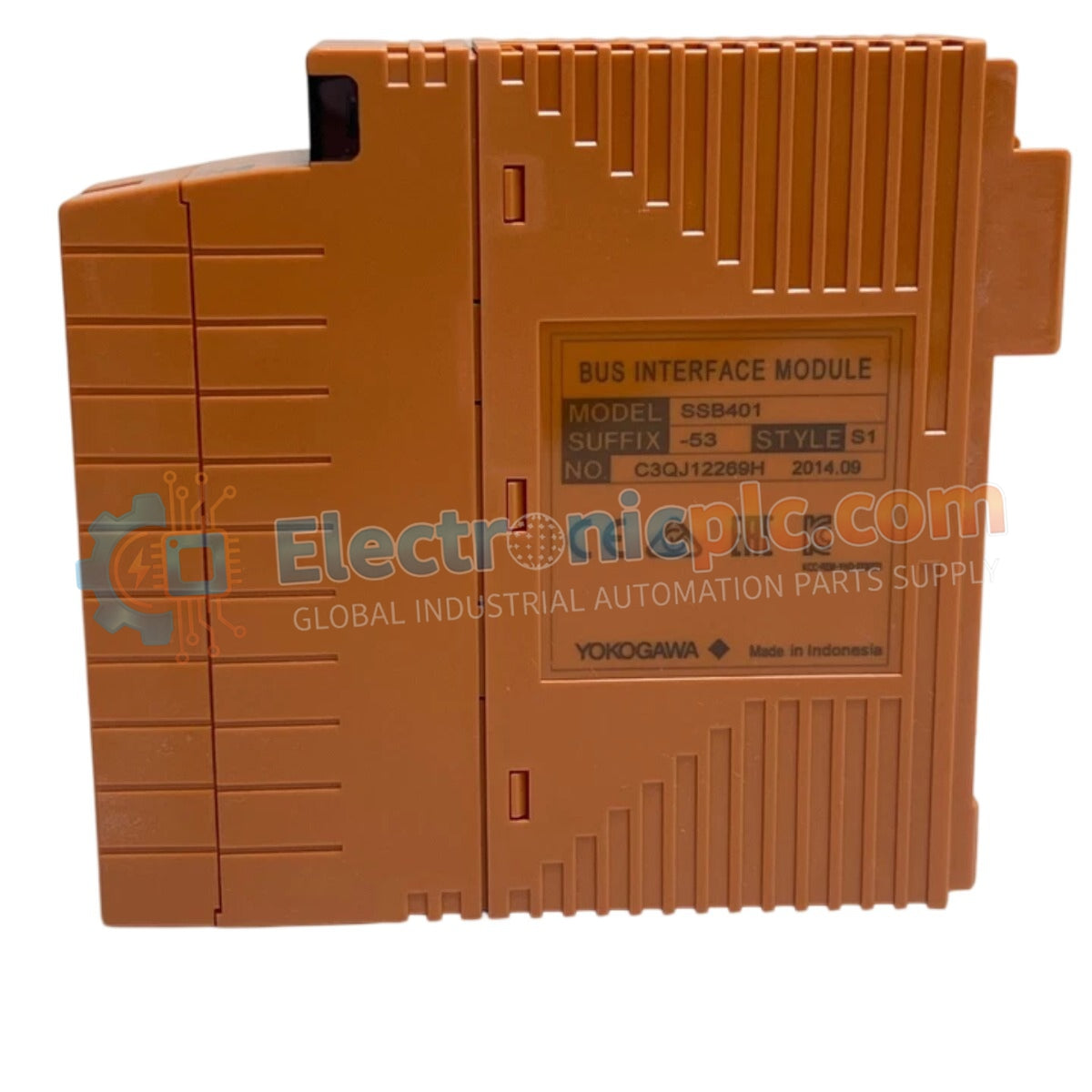
The Yokogawa SSB401-53 (SSB401-53 Bus Interface Module) operates as a dedicated hardware component for managing I/O communication between field control stations and remote slave nodes within distributed control systems. This...
Availability: Low stock: 99 left
Reliable Worldwide Delivery
30-Day Money-Back Guarantee
Need more details? Read our fullShipping PolicyandRefund Policy.


The Yokogawa SSB401-53 (SSB401-53 Bus Interface Module) operates as a dedicated hardware component for managing I/O communication between field control stations and remote slave nodes within distributed control systems. This module serves as the primary interface utilized to execute data synchronization and command routing across the Extended Standard Bus (ESB) architecture in Yokogawa CENTUM platforms.
The SSB401-53 model designation specifies a hardware configuration optimized for high-density I/O bus management. The "-53" suffix denotes a specific revision tailored for enhanced compatibility with cabinet-mounted remote node configurations and standardized DCS bus timing requirements.
| Parameter | Specification |
|---|---|
| Model | SSB401-53 |
| Brand | Yokogawa |
| Origin | JAPAN |
| Weight | 0.2 kg |
| Dimensions | 3.2 cm x 12.7 cm x 12.7 cm |
| Operating Temp | 0 to 60 deg C |
| Power Consumption | 4 W (typical) |
| Interface Type | ESB Bus Slave |
The SSB401-53 integrates into the DCS architecture to provide deterministic communication between the control processor and remote I/O subsystems. It utilizes channel-to-channel isolation to decouple the ESB bus from field-side electrical noise, preventing ground potential differences from affecting the integrity of the data stream. The module supports robust bus timing synchronization, ensuring that high-speed I/O updates are captured without latency, thus maintaining accurate loop control across the distributed network.
Q: Is the SSB401-53 compatible with standard CENTUM VP ESB bus configurations?
A: Yes, the SSB401-53 is specifically engineered for full compatibility with standard CENTUM VP ESB bus master-slave architectures.
Q: Does this module require manual bus termination during installation?
A: Proper bus termination is critical for ESB network stability; users must ensure the final slave node in the bus segment is correctly terminated according to the system installation manual.


