Skip to product information
1 of 3

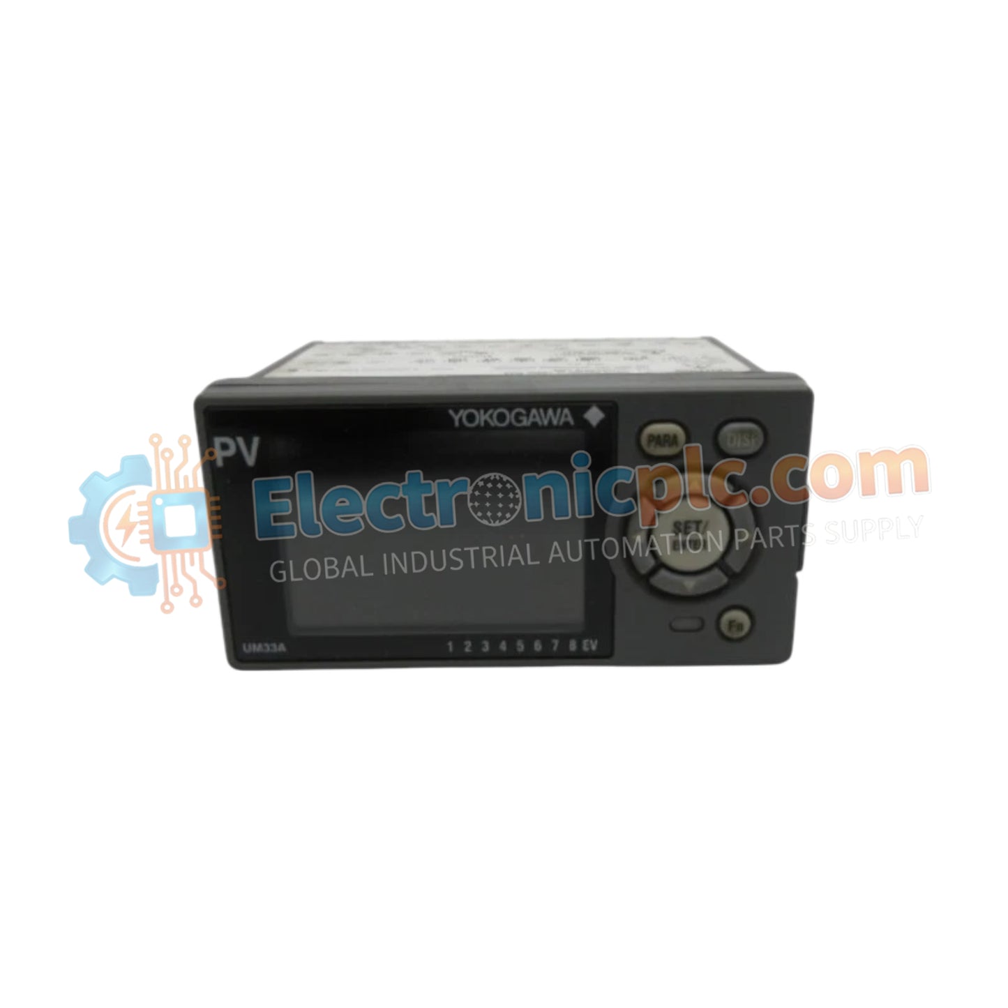
UM33A-000-11/LP Digital Indicator YOKOGAWA

UM33A-000-11/LP Digital Indicator YOKOGAWA

Configured for precision process monitoring and alarm signal management, the YOKOGAWA UM33A-000-11 (UM33A-000-11/LP Digital Indicator) provides direct physical signal processing for industrial instrumentation loops.

Suffix Breakdown & Model Matrix

    ...
23 people are viewing this right now

AvailabilityIn stock

SKU: UM33A-000-11/LP
Vendor: Yokogawa
Category: Digital Indicator
Related Series:

Shipping & Returns

Reliable Worldwide Delivery

  • Carriers: Shipped via DHL, FedEx, UPS, or USPS.
  • Dispatch: Orders processed in 1-2 business days and dispatched within 3-5 business days.
  • Tracking: Full tracking details provided via email upon shipment.

30-Day Money-Back Guarantee

  • Guarantee: 30-day return window for in-stock, factory-sealed products.
  • Condition: Items must be unopened, unused, and in original packaging.
  • Authenticity: We guarantee 100% original and authentic hardware.

Need more details? Read our fullShipping PolicyandRefund Policy.

Authenticity & Warranty

  • Genuine Guarantee: We supply only 100% original, brand-new, and factory-sealed industrial automation parts.
  • Full Coverage: Every component is backed by a 12-month comprehensive warranty from the date of purchase.
  • Traceability: All products come with original factory documentation and accessories for full industrial compliance.

Technical Support & Sourcing

  • Expert Assistance: Our technical team provides free consultation to help you verify compatibility for DCS and PLC systems.
  • Rare Part Sourcing: Specializing in obsolete and hard-to-find components from Allen-Bradley, Siemens, ABB, HIMA, and more.
  • Bulk Inquiries: Contact us at pambo@5gplc.com for volume pricing or customized project quotes.
View full product details

Configured for precision process monitoring and alarm signal management, the YOKOGAWA UM33A-000-11 (UM33A-000-11/LP Digital Indicator) provides direct physical signal processing for industrial instrumentation loops.

Suffix Breakdown & Model Matrix

  • UM33A: Base model for 1/8 DIN digital indicator.
  • -000: Specifies standard hardware functionality without advanced network or custom logic blocks.
  • -11: Defines English default display language and black case color configuration.
  • -LP: Designates the integrated 24 VDC loop power supply option.

Hardware Specifications

Parameter Specification
Model UM33A-000-11/LP
Brand YOKOGAWA
Origin Japan
Weight 0.5 kg
Dimensions 9.6 cm x 4.8 cm x 6.5 cm
Panel Cutout 9.2 cm x 4.5 cm
Operating Temp Not specified
Power Consumption Not specified
Input Type 2-point no-voltage contact or transistor
Output Type 4-20 mA DC or 0-20 mA DC retransmission
Alarm Configuration 3 points (1a contact) + 1 point (1c contact)
Mounting Up to 30 deg above horizontal

Process Control Instrumentation Connectivity

The UM33A utilizes standard 4-20 mA HART loop protocol principles for retransmission, allowing seamless data forwarding to secondary DCS or PLC monitoring nodes. The device provides internal galvanic isolation between the signal input and the retransmission output to prevent ground loops. It features specific alarm logic execution capabilities, ensuring that process deviations are detected and signaled immediately through the independent 1a/1c relay contact architecture.

Frequently Asked Questions

Q: Can the UM33A be mounted in a vertical or downward-tilted orientation?

A: No, mounting is restricted to a maximum of 30 degrees above horizontal. Downward tilting is strictly prohibited to maintain proper heat dissipation and internal component longevity.

Q: How is the 24 VDC loop power supply utilized?

A: The /LP option provides dedicated power to field transmitters directly through the signal loop, eliminating the requirement for external power supplies for standard 4-20 mA loops.

Field Installation Guidelines

  • Verify that the panel cutout dimensions (9.2 cm x 4.5 cm) are exact; undersized cutouts may induce structural stress on the polycarbonate housing.
  • Use M3 screw terminals with square washers for all signal and power connections to ensure low-resistance, vibration-resistant contact.
  • Ensure no downward tilting is present during installation to prevent thermal accumulation within the 1/8 DIN housing.
  • Route signal cabling separately from high-voltage AC lines to mitigate electromagnetic induction, which can cause erratic alarm triggering.
  • Ground the instrument common as per local electrical safety standards to maintain the integrity of the galvanic isolation between input and retransmission stages.