My Cart
0 items
Genuine Automation Parts | Worldwide Express Delivery | 12-Month Warranty — [GET A QUOTE]

The Yokogawa UM33A-000-11, also cataloged as the UM33A Digital Indicator With Alarm, operates as a dedicated hardware component for localized process monitoring and limit state signaling within industrial control panels....
Availability: Low stock: 99 left
Reliable Worldwide Delivery
30-Day Money-Back Guarantee
Need more details? Read our fullShipping PolicyandRefund Policy.


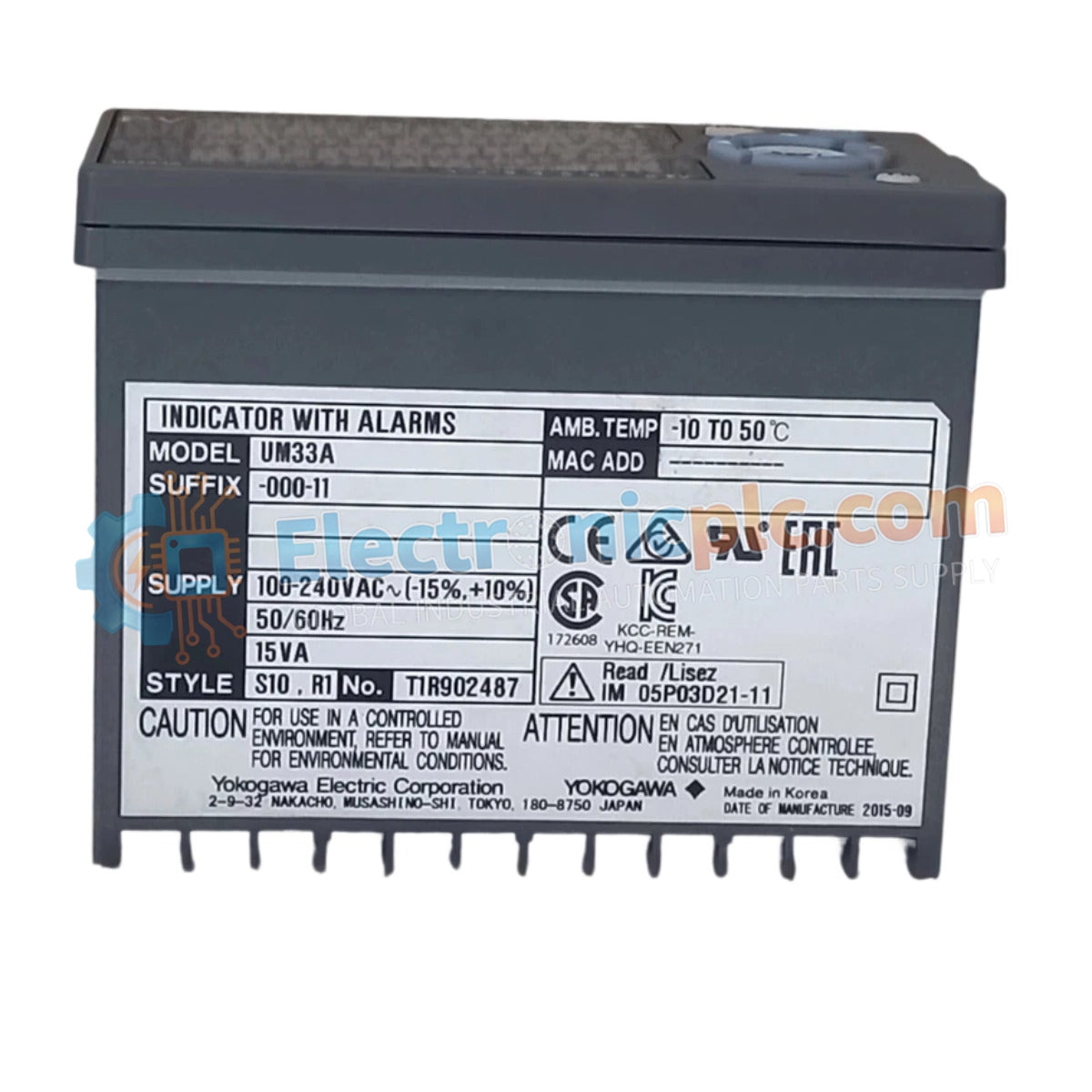
The Yokogawa UM33A-000-11, also cataloged as the UM33A Digital Indicator With Alarm, operates as a dedicated hardware component for localized process monitoring and limit state signaling within industrial control panels. This unit provides direct physical and electrical execution of multi-point alarm monitoring and signal retransmission, ensuring real-time visibility of process variables.
| Suffix / Model | Configuration Detail |
|---|---|
| UM33A | Digital Indicator Base Series |
| -0 | Standard Functions |
| -0 | No Open Network Connectivity |
| -1 | English Display Language |
| 1 | Black (Light Charcoal Gray) Case Color |
| Parameter | Specification |
|---|---|
| Model | UM33A-000-11 |
| Brand | Yokogawa |
| Origin | Japan |
| Weight | 0.5 kg |
| Dimensions | 9.6 cm x 4.8 cm x 6.5 cm |
| Panel Cutout | 9.2 cm x 4.5 cm |
| Operating Temp | -10 deg C to 50 deg C |
| Power Consumption | 15 V DC Loop Power |
| Input Density | 2 Points (Contact/Transistor) |
| Output Density | 1 Retransmission + 4 Alarm Outputs |
The UM33A-000-11 utilizes a high-precision digital processing core to convert sensor inputs into actionable visual data. The retransmission output provides a 4-20 mA DC signal, facilitating integration with secondary recorders or data acquisition systems. The alarm architecture comprises three 1a contact points and one 1c change-over contact point, allowing for flexible safety interlocks or local notification triggers based on pre-defined process setpoints.
Q: Can the UM33A-000-11 be mounted in a downward tilt orientation?
A: No, the installation manual explicitly prohibits downward tilt to prevent thermal accumulation and ensure proper readability of the display. Maximum upward tilt is limited to 30 degrees above the horizontal.
Q: Is the 15 V DC loop power supply isolated from the retransmission output?
A: The retransmission output and loop power supply share the same terminal configuration; users must ensure the total load resistance on the retransmission circuit does not exceed 600 Ω.


