Skip to product information
1 of 3

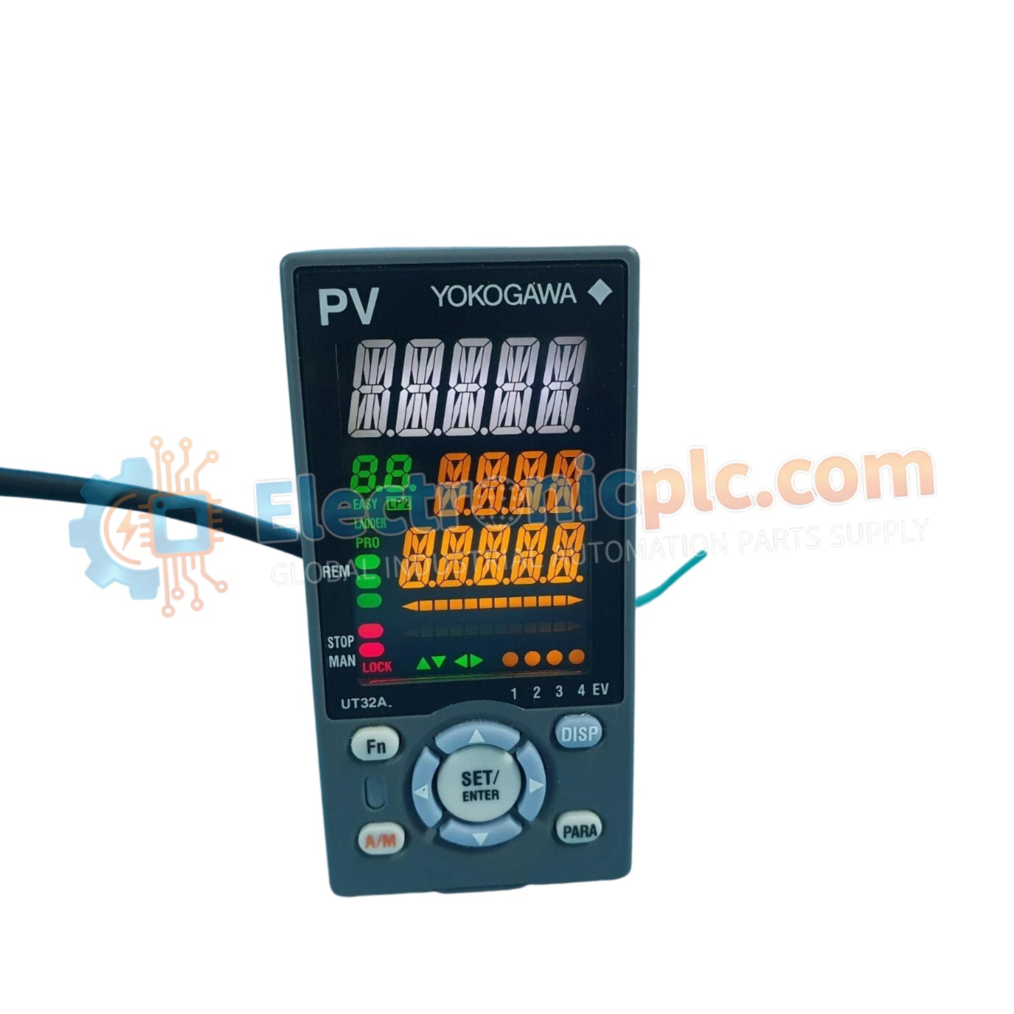
UT32A-010-11-00 Digital Indicating Controller Yokogawa

UT32A-010-11-00 Digital Indicating Controller Yokogawa

The Yokogawa UT32A-010-11-00, also cataloged as the UT32A Digital Indicating Controller, operates as a dedicated hardware component for precision temperature regulation and process variable management within industrial control loops.

Suffix...

25 people are viewing this right now

AvailabilityIn stock

SKU: UT32A-010-11-00
Vendor: Yokogawa

Shipping & Returns

Reliable Worldwide Delivery

  • Carriers: Shipped via DHL, FedEx, UPS, or USPS.
  • Dispatch: Orders processed in 1-2 business days and dispatched within 3-5 business days.
  • Tracking: Full tracking details provided via email upon shipment.

30-Day Money-Back Guarantee

  • Guarantee: 30-day return window for in-stock, factory-sealed products.
  • Condition: Items must be unopened, unused, and in original packaging.
  • Authenticity: We guarantee 100% original and authentic hardware.

Need more details? Read our fullShipping PolicyandRefund Policy.

Authenticity & Warranty

  • Genuine Guarantee: We supply only 100% original, brand-new, and factory-sealed industrial automation parts.
  • Full Coverage: Every component is backed by a 12-month comprehensive warranty from the date of purchase.
  • Traceability: All products come with original factory documentation and accessories for full industrial compliance.

Technical Support & Sourcing

  • Expert Assistance: Our technical team provides free consultation to help you verify compatibility for DCS and PLC systems.
  • Rare Part Sourcing: Specializing in obsolete and hard-to-find components from Allen-Bradley, Siemens, ABB, HIMA, and more.
  • Bulk Inquiries: Contact us at pambo@5gplc.com for volume pricing or customized project quotes.
View full product details

The Yokogawa UT32A-010-11-00, also cataloged as the UT32A Digital Indicating Controller, operates as a dedicated hardware component for precision temperature regulation and process variable management within industrial control loops.

Suffix Breakdown & Model Matrix

  • UT32A: Base model series for digital indicating controllers (1/8 DIN size).
  • 010: Indicates the specific control output and terminal configuration (Single loop standard).
  • 11: Denotes the power supply (100-240 VAC) and input/output configuration options.
  • 00: Represents the standard display and non-customized auxiliary features.

Hardware Specifications

Parameter Specification
Model UT32A-010-11-00
Brand Yokogawa
Origin Japan
Weight 0.25 kg
Dimensions 48 mm x 96 mm x 100 mm
Operating Temp 0 to 50 deg C
Power Consumption 13 VA maximum
Display 14-segment color LCD
Control Modes PID, ON/OFF, Heating/Cooling
Communication RS-485 / Ethernet support

Process Control and Loop Integrity

The integration of 4-20 mA HART loop protocol capabilities within the Yokogawa control architecture ensures precise transmitter interfacing. For high-density process environments, channel-to-channel isolation is maintained to prevent ground loop interference during analog signal acquisition. The controller utilizes cold junction compensation (CJC) when interfacing with thermocouple inputs to maintain measurement accuracy in fluctuating ambient temperature conditions. This ensures that the primary process variable remains stable despite fluctuations in the external thermal environment.

Frequently Asked Questions

Q: Can the UT32A-010-11-00 support hot-swapping during active operation?

A: No. The unit is designed for panel mounting with fixed terminal block connections. Power must be isolated before removing the controller from its housing to prevent circuit damage.

Q: How is the heater break alarm configured for specific load thresholds?

A: The /HA function monitors the current via an external CT (Current Transformer). Thresholds are set within the controller menu based on the nominal heater current; an alarm triggers when current drops below the defined setpoint, indicating a load failure.

Field Installation Guidelines

  • Mounting: Ensure the panel cutout meets the 45 mm x 92 mm requirement. Secure the unit using the provided mounting brackets, applying uniform torque to the screws to prevent chassis deformation.
  • Wiring: Maintain separation between signal input lines and high-voltage power lines to minimize electromagnetic interference. Use shielded twisted-pair cables for RS-485 communication paths.
  • Grounding: The functional earth terminal must be connected to a dedicated ground point to minimize common-mode noise.
  • Environment: Avoid installation in areas with high humidity or corrosive gases. Ensure adequate airflow around the rear terminal area to maintain heat dissipation within the specified operating temperature limits.