Skip to product information
1 of 3

UT35A-001-11-00/LP/DC Digital Indicating Controller YOKOGAWA

UT35A-001-11-00/LP/DC Digital Indicating Controller YOKOGAWA

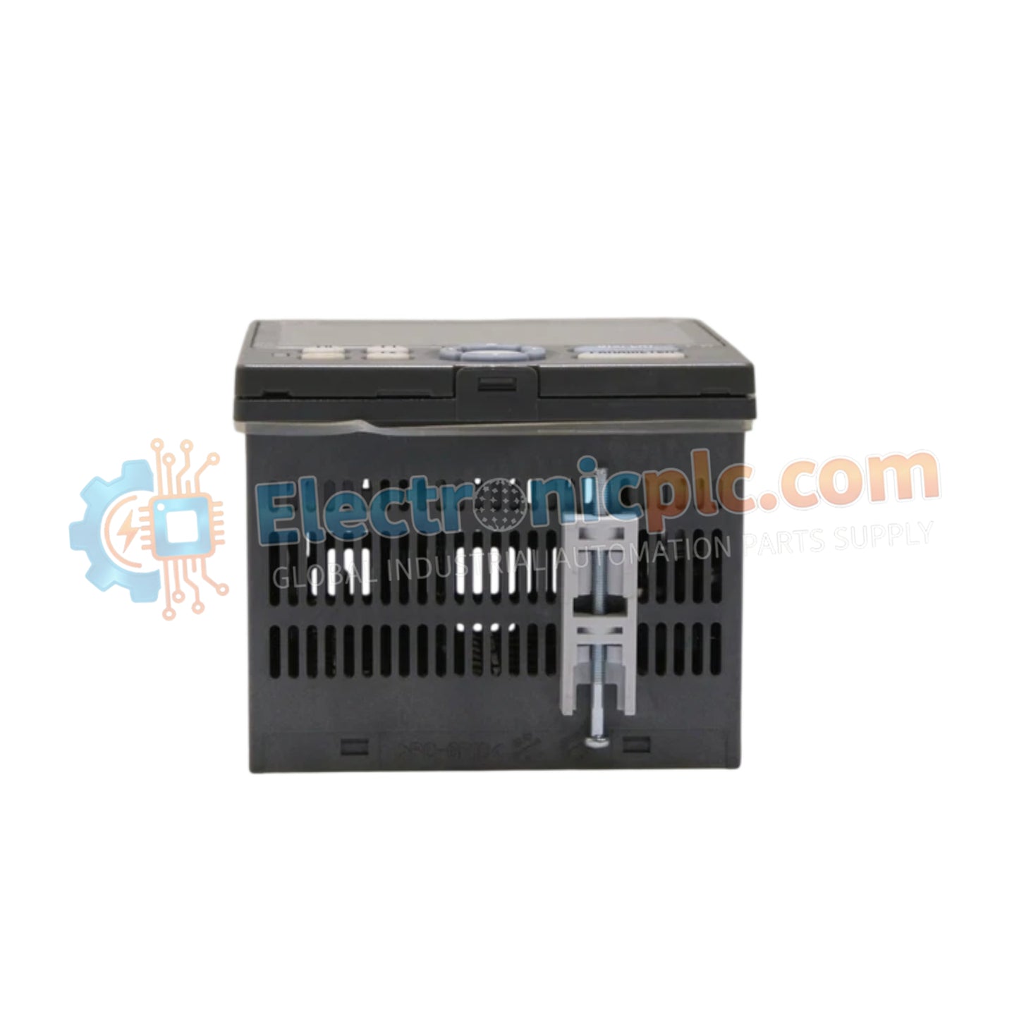
Configured for precision single-loop process management, the YOKOGAWA UT35A-001-11-00/LP/DC (UT35A-001-11-00/LP/DC Digital Indicating Controller) provides direct physical signal processing and setpoint control across distributed instrumentation networks.

Suffix Breakdown & Model Matrix

...
18 people are viewing this right now

AvailabilityIn stock

SKU: UT35A-001-11-00/LP/DC
Vendor: Yokogawa

Shipping & Returns

Reliable Worldwide Delivery

  • Carriers: Shipped via DHL, FedEx, UPS, or USPS.
  • Dispatch: Orders processed in 1-2 business days and dispatched within 3-5 business days.
  • Tracking: Full tracking details provided via email upon shipment.

30-Day Money-Back Guarantee

  • Guarantee: 30-day return window for in-stock, factory-sealed products.
  • Condition: Items must be unopened, unused, and in original packaging.
  • Authenticity: We guarantee 100% original and authentic hardware.

Need more details? Read our fullShipping PolicyandRefund Policy.

Authenticity & Warranty

  • Genuine Guarantee: We supply only 100% original, brand-new, and factory-sealed industrial automation parts.
  • Full Coverage: Every component is backed by a 12-month comprehensive warranty from the date of purchase.
  • Traceability: All products come with original factory documentation and accessories for full industrial compliance.

Technical Support & Sourcing

  • Expert Assistance: Our technical team provides free consultation to help you verify compatibility for DCS and PLC systems.
  • Rare Part Sourcing: Specializing in obsolete and hard-to-find components from Allen-Bradley, Siemens, ABB, HIMA, and more.
  • Bulk Inquiries: Contact us at pambo@5gplc.com for volume pricing or customized project quotes.
View full product details

Configured for precision single-loop process management, the YOKOGAWA UT35A-001-11-00/LP/DC (UT35A-001-11-00/LP/DC Digital Indicating Controller) provides direct physical signal processing and setpoint control across distributed instrumentation networks.

Suffix Breakdown & Model Matrix

  • UT35A: Base model for 1/4 DIN digital indicating controller.
  • -001: Specifies universal input configuration and primary control output logic.
  • -11: Defines standard communication and terminal interface specifications.
  • -00/LP/DC: Designates the integrated loader port, loop power supply, and 24 VDC power input version.

Hardware Specifications

Parameter Specification
Model UT35A-001-11-00/LP/DC
Brand YOKOGAWA
Origin Japan
Weight 0.58kg
Dimensions 96 mm x 96 mm (1/4 DIN)
Operating Temp -10 to 50 deg C
Power Consumption Not specified
Power Supply 24 VDC
Control Period 200 ms
Accuracy +/- 0.1% of reading
Protection NEMA4 / IP66 front panel

Process Control Instrumentation Connectivity

The controller integrates seamlessly into standard process environments utilizing universal input sensing for thermocouples, RTDs, and mA/V signals. It features channel-to-channel isolation principles to ensure input stability against common-mode noise in instrumentation loops. The internal architecture facilitates cold junction compensation (CJC) for temperature inputs, ensuring stable setpoint execution and process variable monitoring via the 3-color 14-segment LCD display.

Frequently Asked Questions

Q: Does the UT35A-001 support ramp and soak profile execution?

A: Yes, the unit includes built-in ramp and soak functionality, allowing for time-based setpoint adjustments without the requirement for external PLC sequence logic.

Q: Is the loader port (/LP) compatible with standard USB-to-serial converters?

A: The /LP loader port requires a dedicated Yokogawa communication cable for interface with the LL50A software. Standard generic serial converters may not provide the necessary voltage levels or signal protocols.

Field Installation Guidelines

  • Verify the 96 mm x 96 mm panel cutout dimensions to ensure the NEMA4 / IP66 gasket provides a proper seal against moisture and dust ingress.
  • Use shielded, twisted-pair cabling for all universal input signals to maintain the 0.1% accuracy rating and mitigate electromagnetic interference (EMI).
  • Ensure the 24 VDC power source is regulated and isolated to prevent voltage transients from affecting the controller internal processing.
  • Route signal wires away from high-current power cables to prevent induction noise, which can cause erratic control output behavior.
  • Confirm that the input type (thermocouple, RTD, or voltage) is correctly selected in the software configuration before applying process variables.