My Cart
0 items
Genuine Automation Parts | Worldwide Express Delivery | 12-Month Warranty — [GET A QUOTE]

Configured for high-speed network integration within CENTUM control system architectures, the YOKOGAWA AIP502/S1 (AIP502 V-Net Coupler Module) provides direct physical execution of bus signal coupling and data propagation across V-Net...
Availability: In stock
Reliable Worldwide Delivery
30-Day Money-Back Guarantee
Need more details? Read our fullShipping PolicyandRefund Policy.


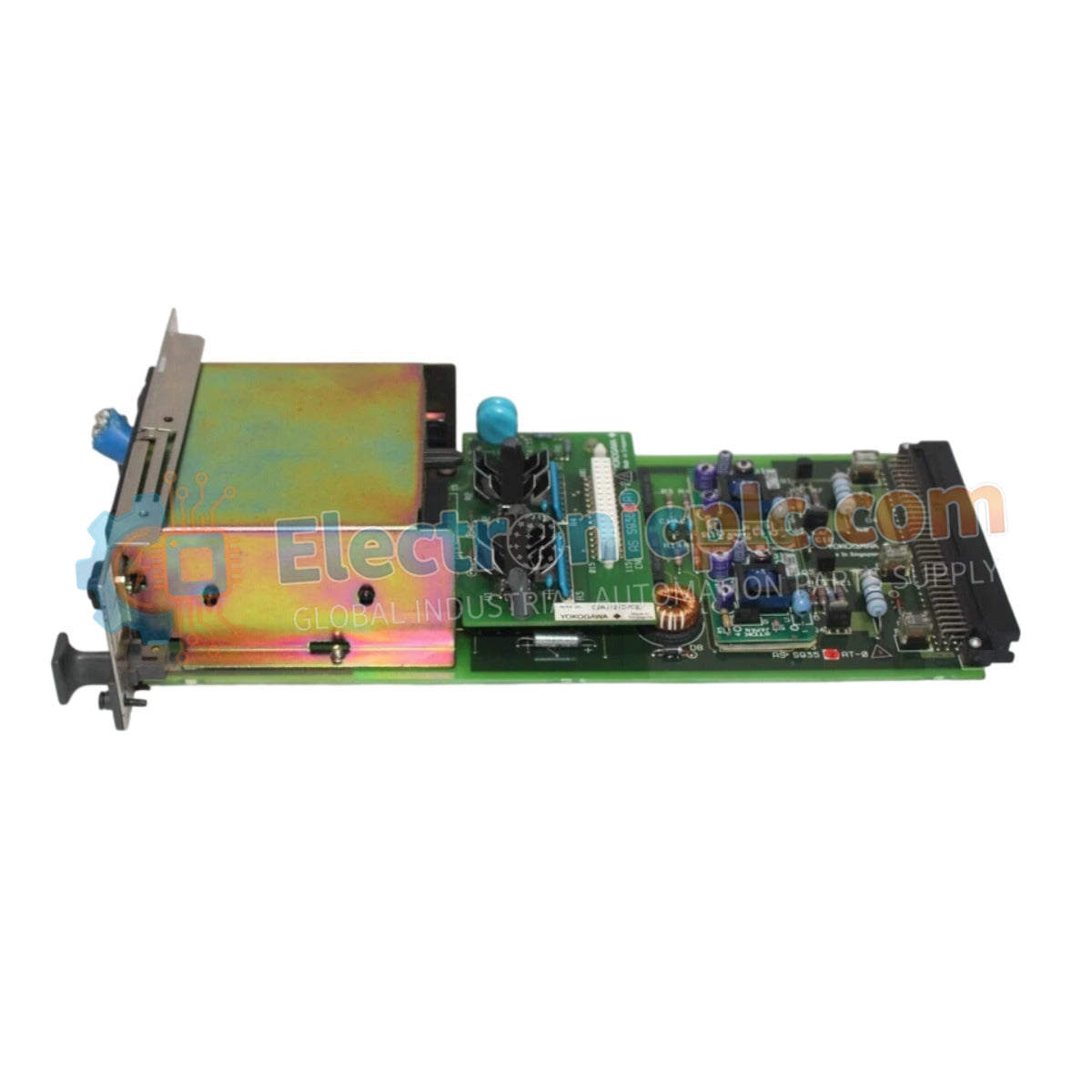
Configured for high-speed network integration within CENTUM control system architectures, the YOKOGAWA AIP502/S1 (AIP502 V-Net Coupler Module) provides direct physical execution of bus signal coupling and data propagation across V-Net control network segments.
The AIP502/S1 utilizes a structured ordering format to define hardware revision and system compatibility. The /S1 suffix indicates the specific hardware iteration optimized for integration with V-Net communication standards, ensuring compatibility with the data throughput and timing requirements of the CENTUM network platform.
| Parameter | Specification |
|---|---|
| Model | AIP502/S1 |
| Brand | YOKOGAWA |
| Origin | Japan |
| Weight | 1.5 kg |
| Dimensions | 2.2 cm x 12.4 cm x 12.6 cm |
| Operating Temp | 0 deg C to 60 deg C |
| Power Consumption | Passive (backplane powered) |
| Module Type | V-Net Coupler Module |
| Interface | V-Net Control Network |
The AIP502/S1 serves as the critical coupling node for the V-Net control bus, facilitating the transmission of process data between geographically distributed field control units (FCU). In DCS environments, maintaining consistent protocol conversion latencies is required to ensure deterministic data exchange and prevent network collisions. The module architecture is designed to handle high-speed V-Net traffic, employing sophisticated signal regeneration to preserve packet integrity across extended network segments while maintaining strict isolation from the local backplane logic.
Q: Is the AIP502/S1 module capable of supporting redundant V-Net configurations?
A: Yes. The module is designed to operate within redundant V-Net architectures. Ensure the system software is configured to recognize the dual-path topology to enable automatic failover in the event of a single-channel communication loss.
Q: How does this module manage bus traffic congestion?
A: The AIP502/S1 utilizes dedicated hardware buffering to manage data flow. By offloading packet arbitration from the main controller CPU, it minimizes transmission delays during periods of high network traffic or broadcast-heavy communication cycles.


