My Cart
0 items
Genuine Automation Parts | Worldwide Express Delivery | 12-Month Warranty — [GET A QUOTE]

The Yokogawa VF702 S1 (VF702 S1 Control Bus Interface Card) is a specialized communication module designed for seamless data integration within Yokogawa CENTUM control architectures. This card acts as the...
Availability: Low stock: 99 left
Reliable Worldwide Delivery
30-Day Money-Back Guarantee
Need more details? Read our fullShipping PolicyandRefund Policy.


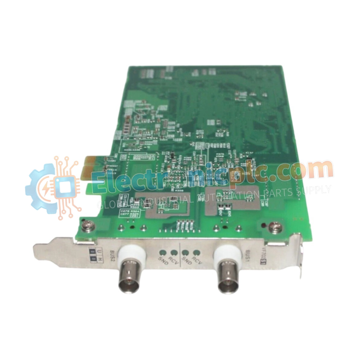
The Yokogawa VF702 S1 (VF702 S1 Control Bus Interface Card) is a specialized communication module designed for seamless data integration within Yokogawa CENTUM control architectures. This card acts as the primary hardware bridge facilitating high-speed, deterministic data exchange between field control stations and the wider control network, ensuring synchronization across distributed processing units.
The VF702 S1 designation represents a refined iteration within the VF702 series. The "S1" suffix indicates an optimized hardware revision featuring updated signaling logic and improved buffer throughput, specifically engineered to enhance compatibility with the high-bandwidth requirements of modernized CENTUM VP system controllers.
| Parameter | Specification |
|---|---|
| Model | VF702 S1 |
| Brand | Yokogawa |
| Origin | Japan |
| Weight | 0.5 kg |
| Dimensions | 2.2 cm x 12.4 cm x 12.6 cm |
| Operating Temp | 0 to 60 deg C |
| Power Consumption | 4.5 W (nominal) |
| Interface Type | Vnet/IP Control Bus |
The VF702 S1 integrates into the DCS architecture to provide deterministic communication—a critical requirement for real-time process control. By managing the flow of data packets between field controllers and the management network, it prevents packet collisions and minimizes communication latency. The card incorporates robust galvanic isolation to decouple the internal station bus from the external control network, effectively mitigating the risk of common-mode noise and ground loops propagating through the control system.
Q: Can the VF702 S1 replace an older VF702 module?
A: In most CENTUM control station setups, the S1 is a functional replacement; however, always verify the control station's firmware revision against the Yokogawa hardware compatibility matrix before deployment.
Q: Does this card support dual-redundant bus paths?
A: Yes, the VF702 S1 is natively designed to be deployed in redundant pairs, enabling automatic failover and high-availability communication for mission-critical industrial processes.


