My Cart
0 items
Genuine Automation Parts | Worldwide Express Delivery | 12-Month Warranty — [GET A QUOTE]

The Yokogawa VI451-10, also cataloged as the VI451-10 Communication Module, operates as a dedicated hardware component for facilitating data transmission and process synchronization within distributed control network architectures. This component...
Availability: Low stock: 99 left
Reliable Worldwide Delivery
30-Day Money-Back Guarantee
Need more details? Read our fullShipping PolicyandRefund Policy.


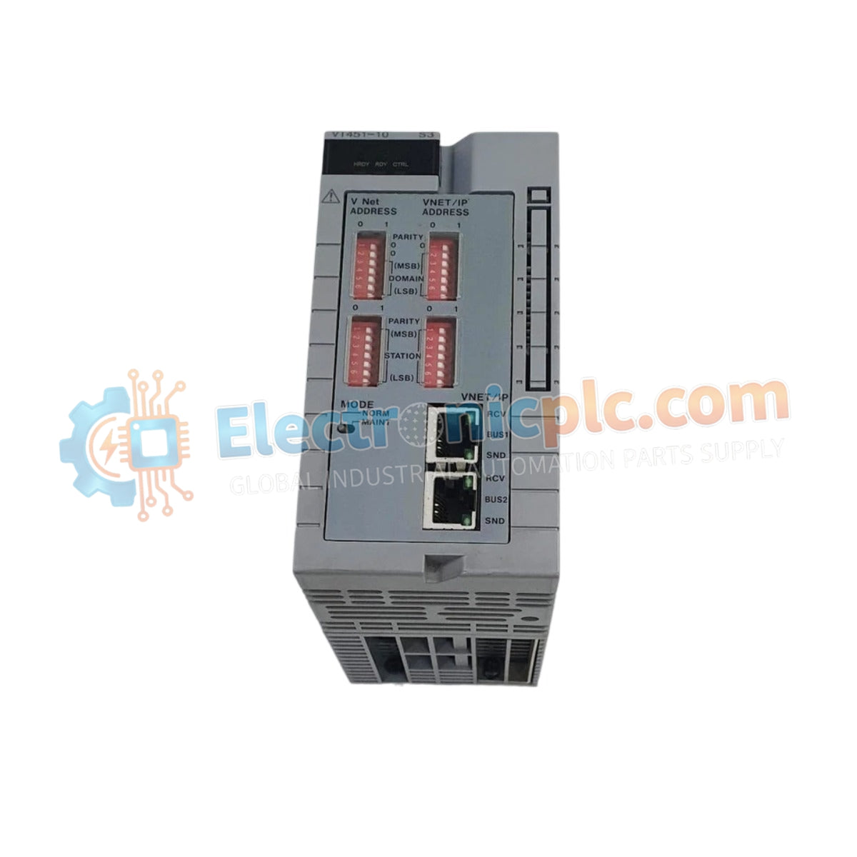
The Yokogawa VI451-10, also cataloged as the VI451-10 Communication Module, operates as a dedicated hardware component for facilitating data transmission and process synchronization within distributed control network architectures. This component serves as the primary communication module utilized to execute high-speed serial or bus data exchanges across Yokogawa CENTUM system platforms.
| Parameter | Specification |
|---|---|
| Model | VI451-10 |
| Brand | Yokogawa |
| Origin | Japan |
| Weight | 0.75 kg |
| Dimensions | 13.2 cm x 5.3 cm x 6.5 cm |
| Operating Temp | 0 to 60 deg C |
| Power Consumption | 5 W (nominal) |
| Module Function | Communication Interface |
The VI451-10 integrates into the DCS architecture to provide reliable data link connectivity between control stations and external field devices. The module utilizes channel-to-channel isolation to decouple the internal control bus from external data transmission paths, preventing common-mode noise or electrical surges from affecting the integrity of the communication channel. Additionally, the module supports firmware flash compatibility, ensuring long-term adaptability for evolving network protocols and communication standards within the Yokogawa control infrastructure.
Q: Is this communication module compatible with redundant system configurations?
A: Yes, the VI451-10 supports integration into redundant control setups, provided the module is mapped correctly within the system configuration database to facilitate automatic switchover.
Q: Can the module firmware be upgraded via the control bus?
A: Yes, the module supports firmware flash compatibility, allowing for updates to be performed through the system maintenance console when the station is in an appropriate maintenance state.


