My Cart
0 items
Genuine Automation Parts | Worldwide Express Delivery | 12-Month Warranty — [GET A QUOTE]

The Yokogawa VI701 S1, also cataloged as the VI701 S1 Interface Card, operates as a dedicated hardware component for facilitating high-speed data exchange and network synchronization within distributed control system...
Availability: Low stock: 99 left
Reliable Worldwide Delivery
30-Day Money-Back Guarantee
Need more details? Read our fullShipping PolicyandRefund Policy.


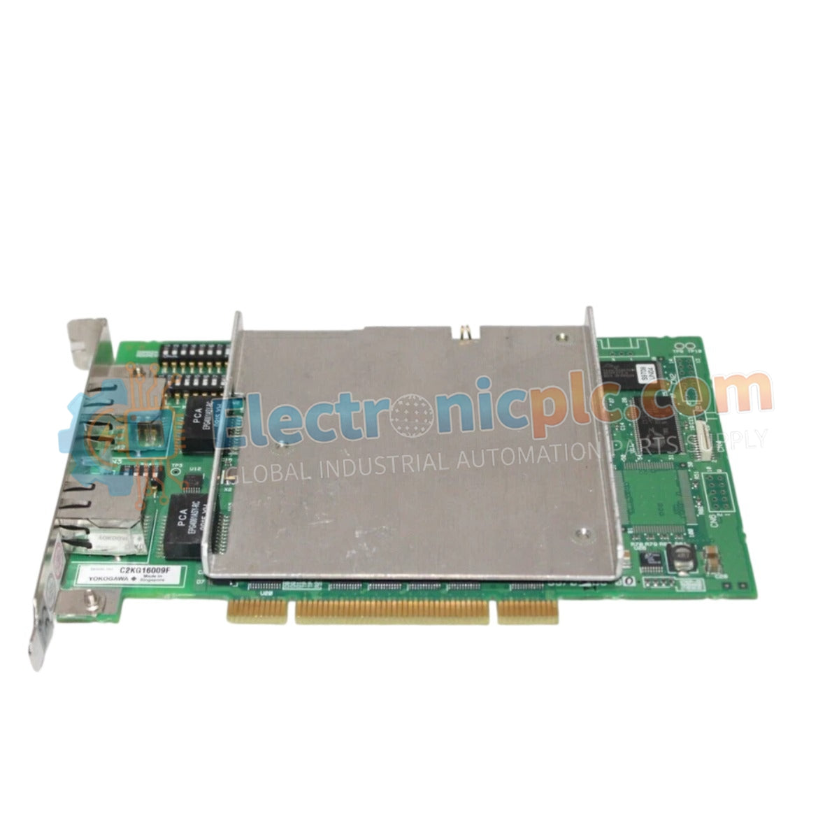
The Yokogawa VI701 S1, also cataloged as the VI701 S1 Interface Card, operates as a dedicated hardware component for facilitating high-speed data exchange and network synchronization within distributed control system platforms. This card serves as the primary communication interface utilized to execute data routing and node-to-node signal verification across Yokogawa CENTUM network platforms.
The VI701 S1 model designation identifies the interface card revision optimized for specific bus timing requirements. The "S1" suffix indicates a hardware configuration tailored for enhanced data throughput and compatibility with revised system backplane communication standards compared to the baseline unit.
| Parameter | Specification |
|---|---|
| Model | VI701 S1 |
| Brand | Yokogawa |
| Origin | Japan |
| Weight | 0.18 kg |
| Dimensions | 2.2 cm x 18.1 cm x 12.7 cm |
| Operating Temp | 0 to 60 deg C |
| Power Consumption | 3 W (typical) |
| Interface Type | System Communication Bus |
The VI701 S1 integrates into the DCS architecture to support deterministic communication protocols, minimizing latencies in data packet delivery. The module utilizes channel-to-channel isolation to decouple the internal communication bus from external field-interface signals, preventing noise propagation from signal lines. Its internal processing architecture supports firmware flash compatibility, allowing for updates to accommodate evolving protocol requirements within the CENTUM infrastructure while maintaining high-speed network reliability.
Q: Is the VI701 S1 compatible with the standard VI701 slot configuration?
A: Yes, the S1 version is designed for direct physical and logical compatibility with standard interface card slots in the control rack, provided the system firmware supports the S1 revision.
Q: What is the procedure for verifying successful data synchronization after installation?
A: After installation, observe the diagnostic LED status on the front panel to confirm a steady link state and verify the communication handshake within the system maintenance utility.


