
My Cart
0 items
Genuine Automation Parts | Worldwide Express Delivery | 12-Month Warranty — [GET A QUOTE]

Configured for pneumatic valve actuation and precise positioning in industrial flow control loops, the Woodward 8200-510 (8200-510 Digital Valve Positioner Module) provides direct physical/electrical execution. This hardware unit processes analog...
Availability: Low stock: 10 left
Reliable Worldwide Delivery
30-Day Money-Back Guarantee
Need more details? Read our fullShipping PolicyandRefund Policy.


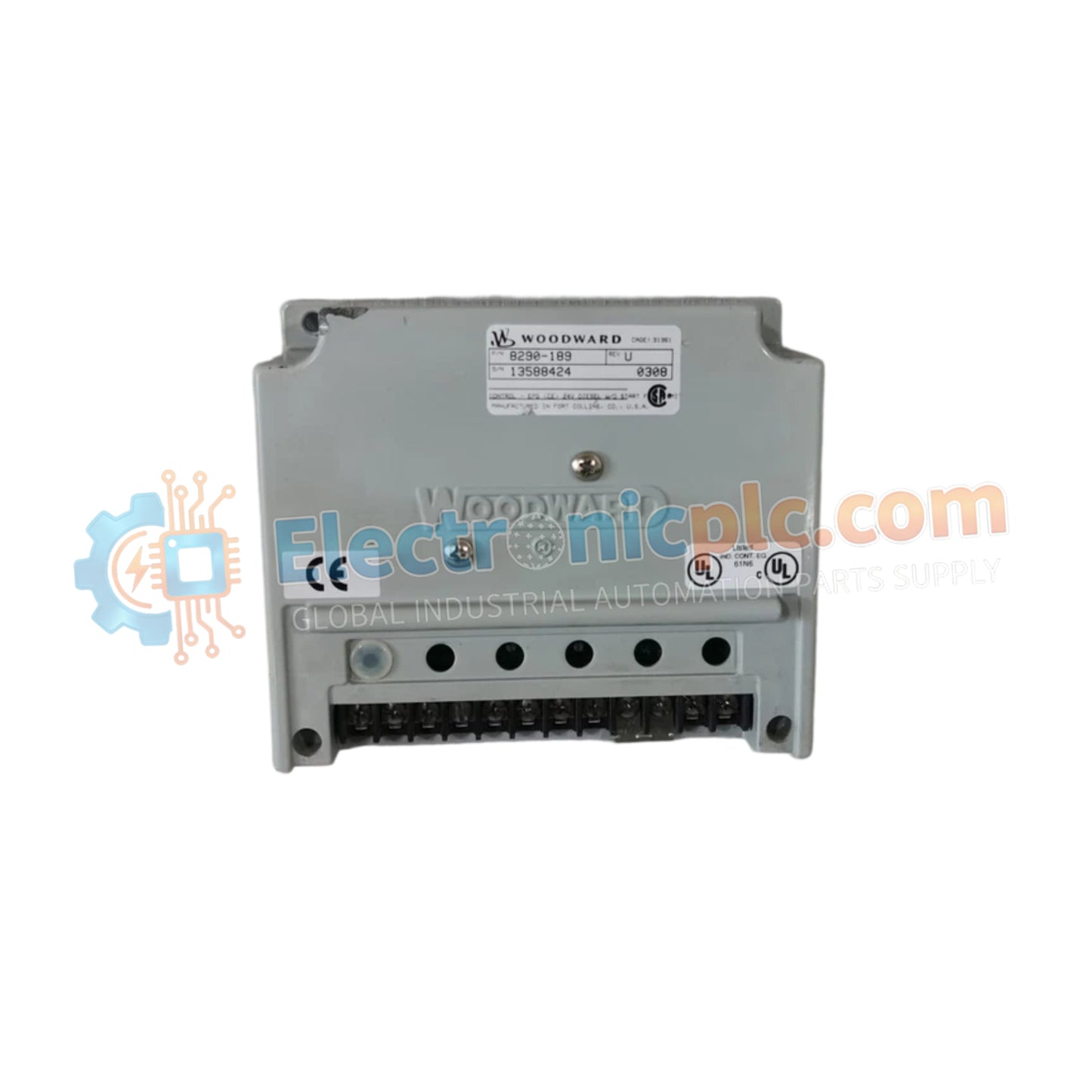
Configured for pneumatic valve actuation and precise positioning in industrial flow control loops, the Woodward 8200-510 (8200-510 Digital Valve Positioner Module) provides direct physical/electrical execution. This hardware unit processes analog control inputs and digital communication commands to regulate pneumatic air pressure, delivering accurate mechanical valve movement for process control applications.
| Parameter | Specification |
|---|---|
| Model | 8200-510 |
| Brand | Woodward |
| Origin | USA |
| Weight | Not specified / Standard DVP housing |
| Dimensions | Not specified / Standard field mounting form factor |
| Operating Temp | -20 deg C to +70 deg C |
| Power Consumption | 24 VDC loop powered / internal logic draw |
| Control Signal | 4-20 mA analog input with HART / Profibus PA / FOUNDATION Fieldbus |
| Air Supply Pressure | 2 to 10 bar (29 to 145 psi) |
The unit incorporates non-contacting inductive position sensors to maintain high-resolution tracking during rapid actuator loop feedback response cycles. Internal thermal heat sink dissipation profiles within the rugged IP66-rated enclosure manage internal component temperatures under full-load operation in exposed industrial environments. Advanced harmonic distortion filtering on the signal and power terminals prevents electromagnetic interference from disrupting precise positioner control loops.
Q: What pneumatic supply pressure range is supported by the valve positioner?
A: The positioner operates reliably with an air supply pressure ranging from 2 to 10 bar (29 to 145 psi).
Q: What type of position feedback mechanism is integrated into the unit?
A: The module utilizes a non-contacting inductive sensor to provide continuous and precise valve stem position feedback without mechanical wear.


